ftDuino Arduino サンプルプログラム集

内部LEDの点滅

/*
  Blink

  Schaltet die interne rote LED des ftDuino für eine Sekunde ein
  und für eine Sekunde aus und wiederholt dies endlos.

  Original:
  http://www.arduino.cc/en/Tutorial/Blink
*/

void setup() {
  // 入出力の設定
  //     ステータスLED   出力
  pinMode(LED_BUILTIN, OUTPUT);
}

// メインの処理
void loop() {
  digitalWrite(LED_BUILTIN, HIGH);   // LED 点灯
  delay(1000);                       // 1秒間停止
  digitalWrite(LED_BUILTIN, LOW);    // LED 消灯
  delay(1000);
}

サンプルプログラム

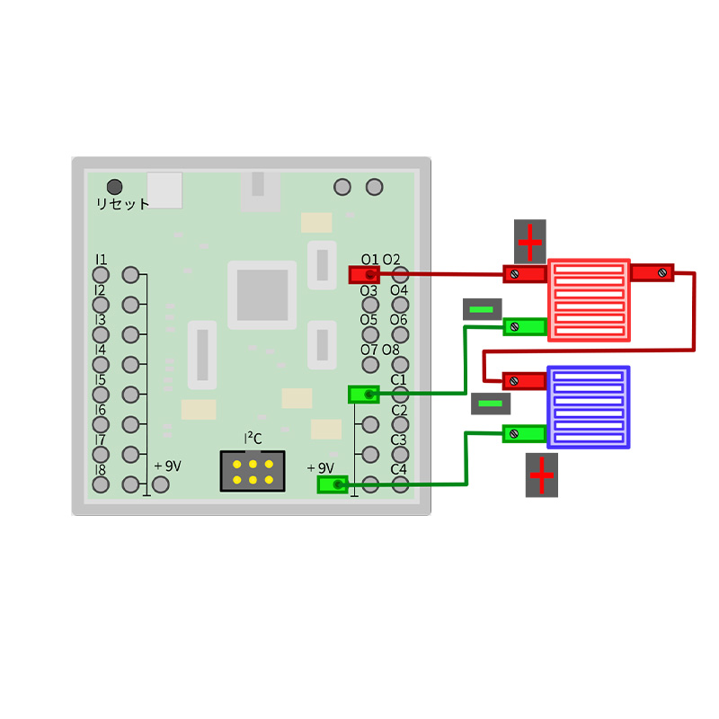
LEDの点滅

// BlinkO1.ino
//
// Blinken einer Lamoe an Ausgang O1
//
// (c) 2018 by Till Harbaum <till@harbaum.org>


//  == インクルード 必要ファイルの読み込み  ==
#include <FtduinoSimple.h>
void setup() {
  // ステータスLED     出力
  pinMode(LED_BUILTIN, OUTPUT);
}

void loop() {
  digitalWrite(LED_BUILTIN, HIGH);  // ステータスLED ON
  ftduino.output_set(Ftduino::O1, Ftduino::HI);  // O1に接続したLED  -- ON
  delay(1000);     //  1秒間停止 

  digitalWrite(LED_BUILTIN, LOW);   // ステータスLED OFF
  ftduino.output_set(Ftduino::O1, Ftduino::LO); // O1に接続したLED  -- OFF
  delay(1000);     //  1秒間停止 
}

サンプルプログラム

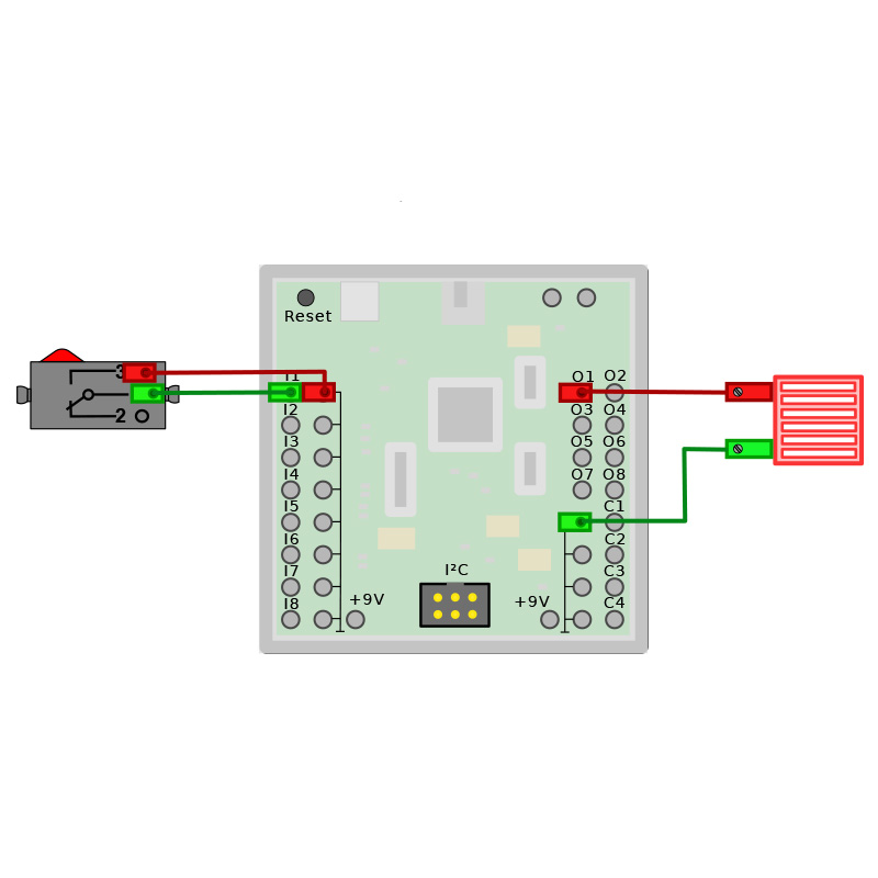
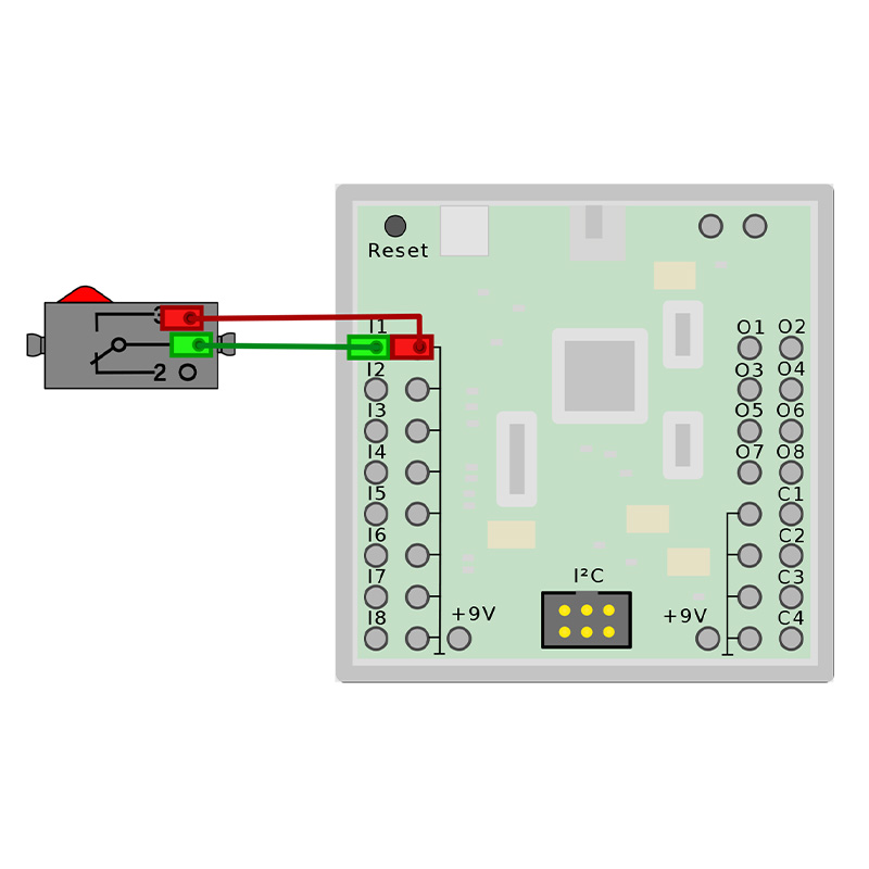
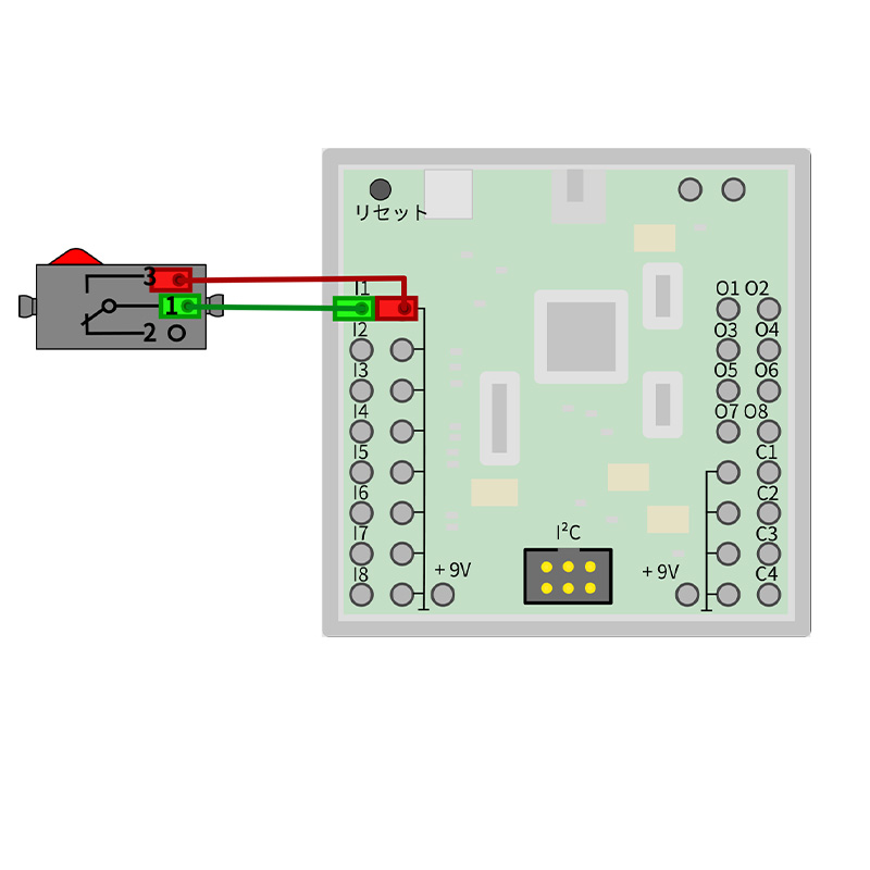
スイッチで10秒LED点灯

/*
  LampTimer - Lampen-Zeitschaltuhr

  (c) 2017 by Till Harbaum <till@harbaum.org>

  Turns a lamp on output O1 on for 10 seconds when a push 
  button on input I1 is being pressed.

  Schaltet eine Lampe an Ausgang O1 für 10 Sekunden ein,
  sobald ein Taster an Eingang I1 gedrückt wird.
*/

// millis()  プログラムの実行を開始した時から現在までの時間をミリ秒単位で返す
//  ==  インクルード 必要ファイルの読み込み ==
#include <FtduinoSimple.h>
uint32_t start_time_zeit = 0;  // タイマー用の変数
void setup() { 
  }

void loop() {
  if(ftduino.input_get(Ftduino::I1)) { // I1 に接続したスイッチが押されたら

    start_time_zeit = millis(); // スタートの時間を変数へ格納
    ftduino.output_set(Ftduino::O1, Ftduino::HI);  //  O1に接続したLED -- 点灯
  }
  if((start_time_zeit != 0) &&        // スタートの時間が0でない かつ
     (millis() > start_time_zeit + 10000)) {  // 10秒以上経過したら
    start_time_zeit = 0;  // タイマー用の変数をリセット

    ftduino.output_set(Ftduino::O1, Ftduino::OFF);  //  O1に接続したLED -- OFF
  }
}

サンプルプログラム

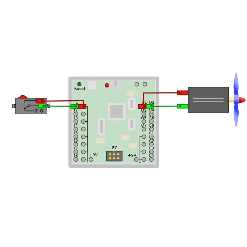
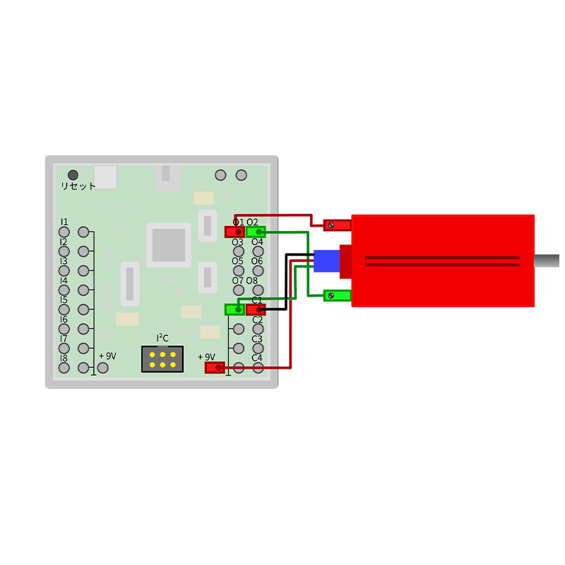
非常停止スイッチ


/*
  EmergencyStop - Not-Aus

  (c) 2017 by Till Harbaum <till@harbaum.org>

  Schaltet einen Ventilator aus, sobald der Not-Aus-Taster
  betätigt wird.
*/

// == インクルード 必要ファイルの読み込み ==
#include <FtduinoSimple.h>

void setup() { 
  // M1 に接続したモーター    左回り
  ftduino.motor_set(Ftduino::M1, Ftduino::LEFT);
  // ステータスLED    出力
  pinMode(LED_BUILTIN, OUTPUT);

  // == 出力 ==
  digitalWrite(LED_BUILTIN, LOW); //  ステータスLED -- OFF
}

void loop() {
  if(ftduino.input_get(Ftduino::I1)) { // I1に接続したスイッチが押されたら
    ftduino.motor_set(Ftduino::M1, Ftduino::BRAKE); // M1に接続したモーターを停止
    digitalWrite(LED_BUILTIN, HIGH);  // ステータスLED -- ON
  }
}

サンプルプログラム

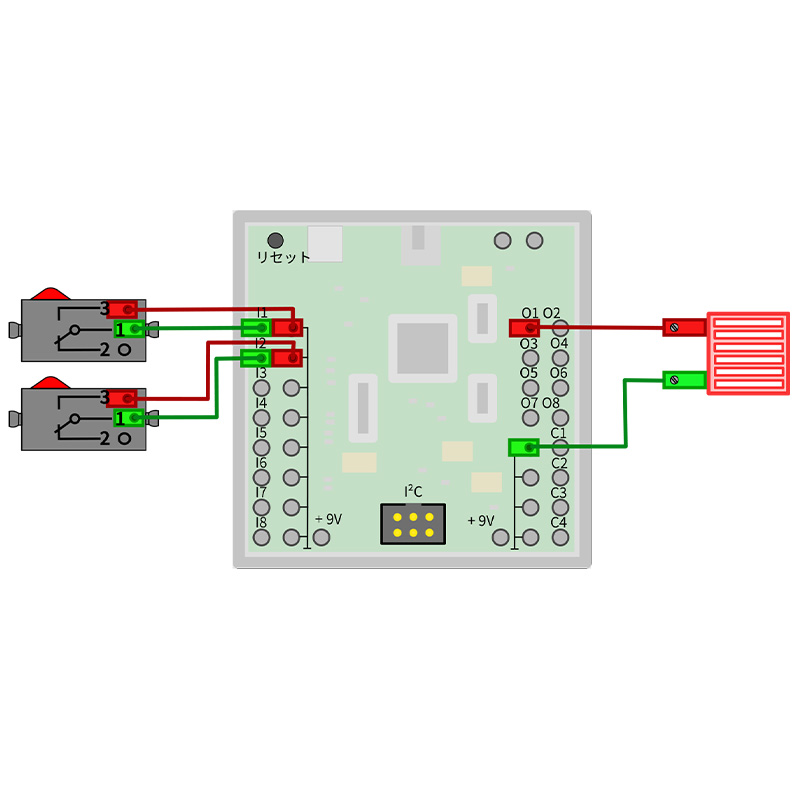
PWM

/*
  Pwm - Pulsweitenmodulation

  (c) 2017 by Till Harbaum <till@harbaum.org>
*/

// == インクルード 必要ファイルの読み込み ==
#include <FtduinoSimple.h>
uint16_t schaltzeit = 8192;   // 8192 を変数へ格納

void setup() {
  Serial.println(9600);
}

// warte という関数の作成
void warte(uint16_t zeit) {
  while (zeit--)
    _delay_us(1000000 / 8192 / 2); // 停止 単位が マイクロ秒
}

void loop() {
  static uint8_t an_aus = false;      // LED のON OFF の切り替えで使用
  static uint8_t i1 = false, i2 = false; // I1,I2 に接続したスイッチの状態を保存する変数

  if (ftduino.input_get(Ftduino::I1)) { // I1のスイッチを押したら
    if (!i1 && (schaltzeit < 8192)) { // I1がTrueのとき かつ 変数schaltzeit が8192 より小さいとき
      // 長押しだと !Tureなのでスルー
      schaltzeit *= 2; // 2倍
      _delay_ms(1); // 1ms停止
    }
    i1 = true; // I1を True にする
  } else // I1が押されていないとき
    i1 = false;  // I1をfalse

  if (ftduino.input_get(Ftduino::I2)) { // I2のスイッチを押したら
    if (!i2 && (schaltzeit > 1)) {  // I2がTrue かつ schaltzeit が1よりも大きいとき
      // 長押しだと !Tureなのでスルー
      schaltzeit /= 2;  // 半分にする
      _delay_ms(1);  // 1ms停止
    }
    i2 = true; // I2 をTrueにする
  } else  // I2 が押されていないとき
    i2 = false;  // I2を false

  if (an_aus) // an_aus が Trueのとき
    ftduino.output_set(Ftduino::O1, Ftduino::HI); // O1に接続したLED -- ON
  else // False のとき
    ftduino.output_set(Ftduino::O1, Ftduino::OFF); //O1に接続したLED -- OFF

  warte(schaltzeit); // 関数を呼び出し
  an_aus = !an_aus;  // an_ausのTrue(またはFalse)反転
  Serial.println("====== I1 =====");
  Serial.println(i1);
}

サンプルプログラム

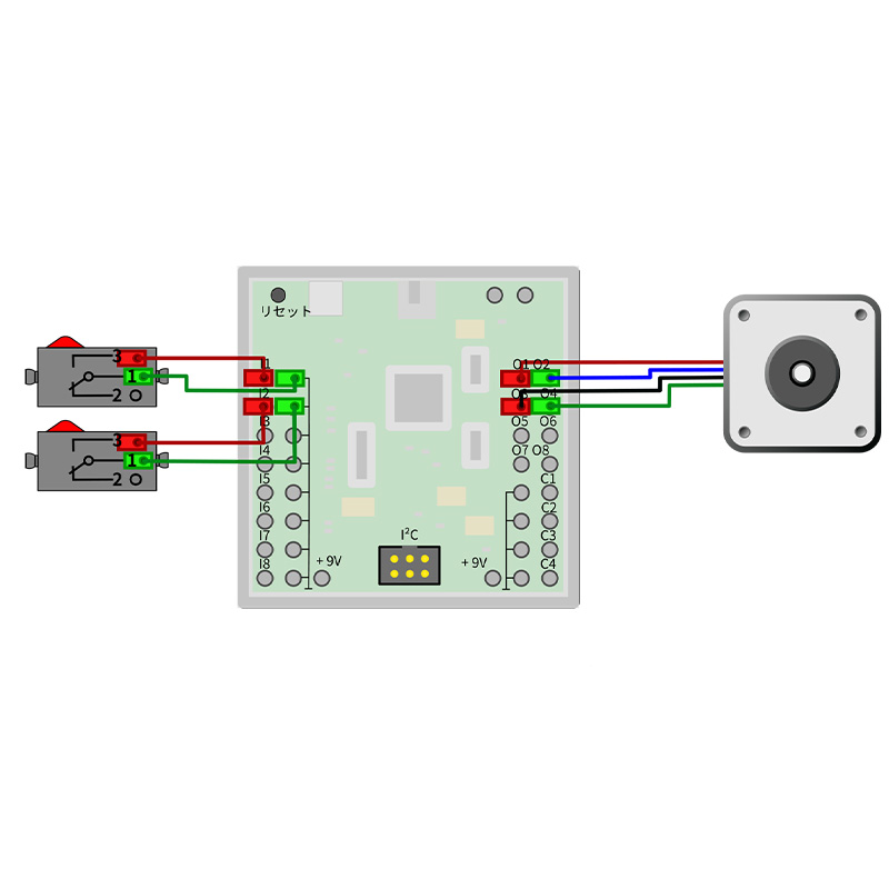
ステッピングモーター

// StepperMotor.ino
// (c) 2018 by Till Harbaum <till@harbaum.org>

//  == インクルード 必要ファイルの読み込み ==
#include <FtduinoSimple.h>
// 200ステップ/秒-> 1回転/秒
// 400ステップ/秒-> 2回転/秒
#define STEPS_PER_SEC  400 
#define US_PER_STEP (1000000/STEPS_PER_SEC)

void setup() {
  // M1を左回転
  ftduino.motor_set(Ftduino::M1, Ftduino::LEFT);
  // M2を右回転
  ftduino.motor_set(Ftduino::M2, Ftduino::LEFT); 
}

void loop() {
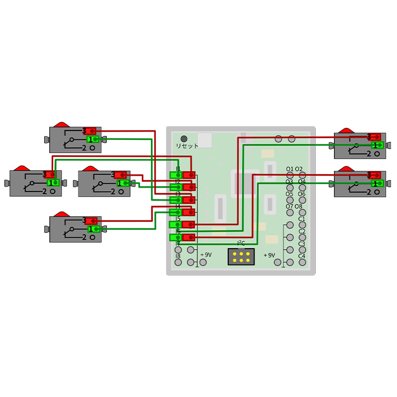
  // I1に接続されたスイッチが押されたら
  while(ftduino.input_get(Ftduino::I1)) {
    // モーターを回転
    ftduino.motor_set(Ftduino::M1, Ftduino::LEFT);
    _delay_us(US_PER_STEP); // 2.5ms 停止
    ftduino.motor_set(Ftduino::M2, Ftduino::LEFT); 
    _delay_us(US_PER_STEP); // 2.5ms 停止
    ftduino.motor_set(Ftduino::M1, Ftduino::RIGHT);
    _delay_us(US_PER_STEP); // 2.5ms 停止
    ftduino.motor_set(Ftduino::M2, Ftduino::RIGHT); 
    _delay_us(US_PER_STEP); // 2.5ms 停止
  }
    
  // Taste an I2 gedrückt
  while(ftduino.input_get(Ftduino::I2)) {
    // I2に接続されたスイッチが押されたら
    ftduino.motor_set(Ftduino::M1, Ftduino::LEFT);
    _delay_us(US_PER_STEP);// 2.5ms 停止
    ftduino.motor_set(Ftduino::M2, Ftduino::RIGHT); 
    _delay_us(US_PER_STEP); // 2.5ms 停止
    ftduino.motor_set(Ftduino::M1, Ftduino::RIGHT);
    _delay_us(US_PER_STEP); // 2.5ms 停止
    ftduino.motor_set(Ftduino::M2, Ftduino::LEFT); 
    _delay_us(US_PER_STEP); // 2.5ms 停止
  }
}

サンプルプログラム

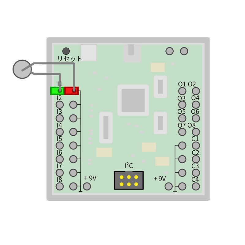
温度センサー

// Temperaure.ino
// Abfrage eines fischertechnik Temperatur-Widerstands an Eingang I1
// (c) 2018 by Till Harbaum <till@harbaum.org>

//  == インクルード 必要ファイルの読み込み ==
#include <Ftduino.h>
#include <math.h>          // 不動小数点の計算に使用

#define K2C 273.15         // 絶対温度 ケルビン へ
#define B 3900.0           // 温度計算で定数として使用
#define R_N 1500.0         // 25°Cの基準温度での抵抗
#define T_N (K2C + 25.0)   // ケルビンでの基準温度

float r2deg(uint16_t r) {
  if (r == 0)
    return NAN;  // 抵抗の値が 0 のとき
  //  抵抗をケルビンに変換します
  float t = T_N * B / (B + T_N * log(r / R_N));
  //  ケルビンを摂氏へ変換します
  return t - K2C;
}

void setup() {
  //  LEDを初期化
  pinMode(LED_BUILTIN, OUTPUT); // 出力
  digitalWrite(LED_BUILTIN, LOW);// 消灯
  // シリアル通信
  Serial.begin(115200);
  while (!Serial);

  ftduino.init();
  // I1に温度センサーを接続
  ftduino.input_set_mode(Ftduino::I1, Ftduino::RESISTANCE);
}

void loop() {
  uint16_t r = ftduino.input_get(Ftduino::I1); // I1からの値を取得

  // シリアルモニタへ出力
  Serial.print("I1: ");
  Serial.print(r2deg(r));  // 関数の呼び出し
  Serial.println(" °C");

  delay(1000); // 1秒停止
}

サンプルプログラム

オンオフトライステート

/*
  OnOffTristate - der dritte Zustand
*/

// == インクルード 必要ファイルの読み込み ==
#include <FtduinoSimple.h>

void setup() { }

void loop() {
  ftduino.output_set(Ftduino::O1, Ftduino::HI); // O1 -- ON
  delay(1000); // 1秒間停止
  ftduino.output_set(Ftduino::O1, Ftduino::LO); // O1 -- OFF
  delay(1000); // 1秒間停止

  // O1をOFFのままにする
  ftduino.output_set(Ftduino::O1, Ftduino::OFF);
  delay(1000);  // 1秒間停止
}

サンプルプログラム

エンコーダーモーター

// MotorBrake.ino
// ftDuino-Experiment zum Bremsverhalten von Elektromotoren

// == インクルード 必要ファイルの読み込み ==
#include <Ftduino.h>

void setup() {
  pinMode(LED_BUILTIN, OUTPUT); // 内部LED -- 出力
  digitalWrite(LED_BUILTIN, HIGH); // 内部LED - ON

  // シリアル通信
  Serial.begin(115200);  // 115200bpsでシリアルポートを開きます
  while (!Serial);

  ftduino.init();
}

void loop() {
  static uint32_t last_led_event = 0;
  // LEDを1秒ごとに点滅
  if ((millis() - last_led_event) >= 1000) { // 1秒を超えたら
    digitalWrite(LED_BUILTIN, HIGH);    // LED - ON
    last_led_event = millis(); // 時間を変数へ格納

  } else if ((millis() - last_led_event) > 50)// 50msを超えたら
    digitalWrite(LED_BUILTIN, LOW);     // LED - OFF

  // 5秒ごとにモーターテストを開始
  static uint32_t last_motor_event = 0;
  if (((millis() - last_motor_event) > 5000)) { // 5秒を超えたら
    static bool brake = true;

    last_motor_event = millis();  // 時間を変数へと格納

    // エンコーダーモーターのブレーキの設定
    ftduino.motor_counter_set_brake(Ftduino::M1, brake);

    /*
      Der TXT-Encoder-Motor liefert 63 1/3 Impulse pro Umdrehung,190 Impulse sind demnach
      drei volle Umdrehungen
    */

    // motor_counter(ポート, モード, pwm, カウンター)
    ftduino.motor_counter(Ftduino::M1, Ftduino::LEFT, Ftduino::MAX, 190);

    //シリアルモニタへ出力
    Serial.println("エンジンM1 == 始動 ==");
    Serial.println("エンコーダーパルスを待っています...");

    //  エンコーダモーターカウンタの評価
    while (ftduino.motor_counter_active(Ftduino::M1));

    if (brake)
      Serial.println("モーターがアクティブブレーキをかけらています --オンラインを待ちます--");
    else
      Serial.println("エンジンを停止 --実行を待ちます --");

    delay(1000);// 1秒間停止

    Serial.print("カウンターステータス: ");
    // C1の カウンター入力のステータス読み取り
    Serial.print(ftduino.counter_get(Ftduino::C1));

    Serial.println("-- INPULSE --");

    //ブレーキの有無にかかわらず交互にテスト
    // brakeを反転
    brake = !brake;
  }
}

サンプルプログラム

キーボードメッセージ

/*
  KeyboardMessage - USB-Tastatur
  Der ftDuino gibt sich als USB-Tastatur aus und "tippt" eine Nachricht, sobald
  ein Taster an Eingang I1 für mindestens 10 Millisekunden gedrückt wird.
  Basierend auf dem Sketch:
  http://www.arduino.cc/en/Tutorial/KeyboardMessage
  Dieser Beispielcode ist Public-Domain.
*/
// == インクルード 必要ファイルの読み込み ==
#include <FtduinoSimple.h>
#include <Keyboard.h>

unsigned long lastButtonEvent = 0;
uint16_t previousButtonState = Ftduino::OFF; // スイッチの状態を格納する変数

void setup() {
  // キーボードの制御を初期化
  Keyboard.begin();
}
void loop() {
  // I1に接続されたスイッチの読み取り
  uint16_t buttonState = ftduino.input_get(Ftduino::I1);
  
  // スイッチの状態が変化したら
  if(buttonState != previousButtonState) {
    lastButtonEvent = millis();// 時間を格納

    previousButtonState = buttonState; // スイッチの状態を更新
  }

 // lasutButtonEventに数値が格納されている状態 かつ
 // 10msを超えていたら
  if(lastButtonEvent && ((millis() - lastButtonEvent) > 10)) {
 
    lastButtonEvent = 0; // 時間をリセット

    if(buttonState) { // スイッチの状態をみる変数をチェックして 押されている状態なら

      // メッセージ
      Keyboard.println("Hello ftDuino!!");
    }
  }
}

サンプルプログラム

USBゲームパッド

/*
   GamePad.ino - eine einfache Gamepad-Imlementierung für
   den ftDuino.
*/
// == インクルード 必要ファイルの読み込み ==
#include <FtduinoSimple.h>
#include "HidGamePad.h"

void setup() {
  // HidGamePadを初期化
  HidGamePad.begin();
  Serial.println(115200);
}

void loop() {
  static int8_t x_axis = 0; // X軸の値を格納
  static int8_t y_axis = 0; // Y軸の値を格納
  static uint8_t buttons = 0; // スイッチの状態を格納

  // I1のスイッチが押さていない かつ I2のスイッチが押されていない   かつ  X軸の値が0でない    とき
  if (!ftduino.input_get(Ftduino::I1) && !ftduino.input_get(Ftduino::I2) && x_axis != 0) {
    x_axis = 0; // x軸の値を0へ
    HidGamePad.setXAxis(x_axis); // X軸の値をセット
  }

  // I1が押されている  かつ    I2が押されていない      かつ X軸の値が -127でないとき
  if (ftduino.input_get(Ftduino::I1) && !ftduino.input_get(Ftduino::I2) && x_axis != -127) {
    x_axis = -127; // x軸の値を -127へ
    HidGamePad.setXAxis(x_axis); // x軸の値をセット
  }

  // I1が押されていない  かつ    I2が押されている     かつ X軸の値が 127でないとき
  if (!ftduino.input_get(Ftduino::I1) && ftduino.input_get(Ftduino::I2) && x_axis != 127) {
    x_axis = 127;  // x軸の値を127へ
    HidGamePad.setXAxis(x_axis); // x軸の値をセット
  }

  // I3が押されていない   かつ    I4が押されていない     かつ Y軸の値が 0でないとき
  if (!ftduino.input_get(Ftduino::I3) && !ftduino.input_get(Ftduino::I4) && y_axis != 0) {
    y_axis = 0; // Y軸の値を 0へ
    HidGamePad.setYAxis(y_axis); // Y軸の値をセット
  }

  // I3が押されていrく   かつ    I4が押されていない      かつ Y軸の値が -127でないとき
  if (ftduino.input_get(Ftduino::I3) && !ftduino.input_get(Ftduino::I4) && y_axis != -127) {
    y_axis = -127; // Y軸の値を -127へ
    HidGamePad.setYAxis(y_axis); // Y軸へ値をセット
  }

  // I3が押されていない   かつ    I4が押されている     かつ X軸の値が 127でないとき
  if (!ftduino.input_get(Ftduino::I3) && ftduino.input_get(Ftduino::I4) && y_axis != 127) {
    y_axis = 127;  // Y軸の値を 127へ
    HidGamePad.setYAxis(y_axis);  // Y軸の値をセット
  }

  // I5が押されていない  かつ   (押されていないとき)
  if (!ftduino.input_get(Ftduino::I5) && (buttons & 1)) {
    buttons &= ~1; // buttons に0 を代入
    HidGamePad.setButton(0, buttons & 1); // 値をセット

  }

  // I5が押されていない   かつ  (押されたとき)
  if (ftduino.input_get(Ftduino::I5) && !(buttons & 1)) {
    buttons |= 1; // buttons に 1 を代入
    HidGamePad.setButton(0, buttons & 1); // 値をセット

  }

  // I6が押されている  かつ  (押されていないとき)
  if (!ftduino.input_get(Ftduino::I6) && (buttons & 2)) {
    buttons &= ~2;// buttons に 0 を代入
    HidGamePad.setButton(1, buttons & 2); // 値をセット

  }

  // I6が押されていない   かつ    (押されたとき)
  if (ftduino.input_get(Ftduino::I6) && !(buttons & 2)) {
    buttons |= 2;// buttons に 0 を代入
    HidGamePad.setButton(1, buttons & 2); // 値をセット
  }
}

---------------------------------------------------------------------------------- // HidGamePad.cpp
/*
*/

#include "HidGamePad.h"

#define REPORT_ID   3
#define REPORT_SIZE 3

static const uint8_t _hidReportDescriptor[] PROGMEM = {
  0x05, 0x01,                // USAGE_PAGE (Generic Desktop)
  0x09, 0x05,                // USAGE (Gamepad)
  0xa1, 0x01,                // COLLECTION (Application)
  0x85, REPORT_ID,           //   REPORT_ID(3)
  0x09, 0x01,                //   USAGE (Pointer)
  0xa1, 0x00,                //   COLLECTION (Physical)
  0x09, 0x30,                //     USAGE (X)
  0x09, 0x31,                //     USAGE (Y)
  0x15, 0x00,                //     LOGICAL_MINIMUM(0)
  0x26, 0xff, 0x00,          //     LOGICAL_MAXIMUM(255)
  0x35, 0x00,                //     PHYSICAL_MINIMUM(0)
  0x46, 0xff, 0x00,          //     PHYSICAL_MAXIMUM(255)
  0x75, 0x08,                //     REPORT_SIZE(8)
  0x95, 0x02,                //     REPORT_COUNT(2)
  0x81, 0x02,                //     INPUT (Data,Var,Abs)
  0xc0,                      //   END_COLLECTION
  0x05, 0x09,                //   USAGE_PAGE (Button)
  0x19, 0x01,                //   USAGE_MINIMUM (Button 1)
  0x29, 0x02,                //   USAGE_MAXIMUM (Button 2)
  0x15, 0x00,                //   LOGICAL_MINIMUM(0)
  0x25, 0x01,                //   LOGICAL_MAXIMUM(1)
  0x95, 0x02,                //   REPORT_COUNT(2)
  0x75, 0x01,                //   REPORT_SIZE(1)
  0x81, 0x02,                //   INPUT (Data,Var,Abs)
  0x95, 0x06,                //   REPORT_COUNT(6)
  0x81, 0x03,                //   INPUT (Const,Var,Abs)
  0xc0                       // END_COLLECTION
};

HidGamePad_::HidGamePad_() {
	// Setup HID report structure
	static HIDSubDescriptor node(_hidReportDescriptor, sizeof(_hidReportDescriptor));
	HID().AppendDescriptor(&node);
	
	// Initalize State
	xAxis = 0;
	yAxis = 0;
	buttons = 0;
}

void HidGamePad_::begin() {
	sendState();
}

void HidGamePad_::end() {
}

void HidGamePad_::setButton(uint8_t button, bool value) {
  if(value) bitSet(buttons, button);
  else      bitClear(buttons, button);
  
  sendState();
}

void HidGamePad_::setXAxis(int8_t value) {
	xAxis = value;
	sendState();
}

void HidGamePad_::setYAxis(int8_t value) {
	yAxis = value;
	sendState();
}

void HidGamePad_::sendState() {
	uint8_t report[REPORT_SIZE];

  // joystick rests in the center with no button pressed
  report[0] = xAxis + 127;
  report[1] = yAxis + 127;
	report[2] = buttons;		

	// HID().SendReport(Report number, array of values in same order as HID descriptor, length)
	HID().SendReport(REPORT_ID, report, REPORT_SIZE);
}

HidGamePad_ HidGamePad;

------------------------------------------------------------------------- // HideGamePad.h
/*
*/

#ifndef HIDGAMEPAD_h
#define HIDGAMEPAD_h

#include <HID.h>

class HidGamePad_ {
public:
	HidGamePad_();

	void begin();
	void end();

	void setXAxis(int8_t value);
	void setYAxis(int8_t value);
	void setButton(uint8_t button, bool value);
	void sendState();
 
private:
  int8_t   xAxis;
  int8_t   yAxis;
  uint8_t  buttons;
};

extern HidGamePad_ HidGamePad;
#endif

サンプルプログラム

デバウンス

/*
  Debounce

  Demonstriert Tastenprellen
*/

// == インクルード 必要ファイルの読み込み ==
#include <FtduinoSimple.h>


void setup() {
  Serial.begin(9600);// シリアル通信
  while (!Serial);
  Serial.println("ftDuinoキーバウンスの例"); // シリアルモニタへ出力
}

uint8_t letzter_zustand = false;
uint8_t wechselzaehler = 0;

void loop() {
  uint8_t zustand = ftduino.input_get(Ftduino::I1);  //I1 の値を読み取り

  if (zustand != letzter_zustand) {       // 状態が違うならば
    wechselzaehler = wechselzaehler + 1;   // カウントを増やす

    //  シリアルモニタへ出力
    Serial.print("I1 ");                   
    Serial.print(wechselzaehler);
    Serial.println("-- 変化しました。-- ");
    letzter_zustand = zustand;  // 新しい状態を格納    
  }
}

サンプルプログラム

ブザー

// == インクルード 必要ファイルの読み込み ==
#include <FtduinoSimple.h>
#include "pitches.h"

// メロディーの配列
int melody[] = {
  NOTE_C4, NOTE_G3, NOTE_G3, NOTE_A3, NOTE_G3, 0, NOTE_B3, NOTE_C4
};
// メロディーの長さに注意
int noteDurations[] = {
  4, 8, 8, 4, 4, 4, 4, 4
};

void setup() {
  // 11を出力に
  pinMode(11, OUTPUT);
}

void loop() {
  //  配列をループ
  for (int thisNote = 0; thisNote < 8; thisNote++) {
    int noteDuration = 1000 / noteDurations[thisNote];  // 音を出す時間を計算
    tone(11, melody[thisNote], noteDuration);  // melody[thisNote番目] の音を noteDurationミリ秒 出力する

    int pauseBetweenNotes = noteDuration * 1.30; // 停止時間を計算
    delay(pauseBetweenNotes); // pauseBetweenNotes 時間停止
  }
  delay(1000); // 1秒間停止
}

--------------------------------------------------------------------- // pitches.h
/*************************************************
 * Public Constants
 *************************************************/

#define NOTE_B0  31
#define NOTE_C1  33
#define NOTE_CS1 35
#define NOTE_D1  37
#define NOTE_DS1 39
#define NOTE_E1  41
#define NOTE_F1  44
#define NOTE_FS1 46
#define NOTE_G1  49
#define NOTE_GS1 52
#define NOTE_A1  55
#define NOTE_AS1 58
#define NOTE_B1  62
#define NOTE_C2  65
#define NOTE_CS2 69
#define NOTE_D2  73
#define NOTE_DS2 78
#define NOTE_E2  82
#define NOTE_F2  87
#define NOTE_FS2 93
#define NOTE_G2  98
#define NOTE_GS2 104
#define NOTE_A2  110
#define NOTE_AS2 117
#define NOTE_B2  123
#define NOTE_C3  131
#define NOTE_CS3 139
#define NOTE_D3  147
#define NOTE_DS3 156
#define NOTE_E3  165
#define NOTE_F3  175
#define NOTE_FS3 185
#define NOTE_G3  196
#define NOTE_GS3 208
#define NOTE_A3  220
#define NOTE_AS3 233
#define NOTE_B3  247
#define NOTE_C4  262
#define NOTE_CS4 277
#define NOTE_D4  294
#define NOTE_DS4 311
#define NOTE_E4  330
#define NOTE_F4  349
#define NOTE_FS4 370
#define NOTE_G4  392
#define NOTE_GS4 415
#define NOTE_A4  440
#define NOTE_AS4 466
#define NOTE_B4  494
#define NOTE_C5  523
#define NOTE_CS5 554
#define NOTE_D5  587
#define NOTE_DS5 622
#define NOTE_E5  659
#define NOTE_F5  698
#define NOTE_FS5 740
#define NOTE_G5  784
#define NOTE_GS5 831
#define NOTE_A5  880
#define NOTE_AS5 932
#define NOTE_B5  988
#define NOTE_C6  1047
#define NOTE_CS6 1109
#define NOTE_D6  1175
#define NOTE_DS6 1245
#define NOTE_E6  1319
#define NOTE_F6  1397
#define NOTE_FS6 1480
#define NOTE_G6  1568
#define NOTE_GS6 1661
#define NOTE_A6  1760
#define NOTE_AS6 1865
#define NOTE_B6  1976
#define NOTE_C7  2093
#define NOTE_CS7 2217
#define NOTE_D7  2349
#define NOTE_DS7 2489
#define NOTE_E7  2637
#define NOTE_F7  2794
#define NOTE_FS7 2960
#define NOTE_G7  3136
#define NOTE_GS7 3322
#define NOTE_A7  3520
#define NOTE_AS7 3729
#define NOTE_B7  3951
#define NOTE_C8  4186
#define NOTE_CS8 4435
#define NOTE_D8  4699
#define NOTE_DS8 4978

サンプルプログラム

コンソール画面でLED点灯

/**
 * Creating an instance of WebUSBSerial will add an additional USB interface to
 * the device that is marked as vendor-specific (rather than USB CDC-ACM) and
 * is therefore accessible to the browser.
 *
 * The URL here provides a hint to the browser about what page the user should
 * navigate to to interact with the device.
 */

//  == インクルード 必要ファイルの読み込み ==
#include <WebUSB.h>

#if USB_VERSION != 0x210  // USB2.1
#error "Bitte board 'ftDuino (WebUSB)' auswählen"
#endif

// WebUSBプロジェクトのURL
WebUSB WebUSBSerial(1 /* https:// */, "harbaum.github.io/ftduino/webusb/console");

#define Serial WebUSBSerial

const int ledPin = LED_BUILTIN;    //内部の赤色LED

void setup() {
  while (!Serial) {
    ;
  }
  Serial.begin(9600);
  // コンソール画面へ出力
  Serial.write("Sketch begins.\r\n> ");
  Serial.write("Press 'H' or 'L' for LED\r\n> ");
  Serial.flush();// データの送受信が全て完了するまで待機
  pinMode(ledPin, OUTPUT); // 内部の赤色LEDを出力へ
}

void loop() {
  // USB接続されているとき
  if (Serial && Serial.available()) {
    int byte = Serial.read();// データの読み取り
    Serial.write(byte);// 書き込み
    
    if (byte == 'H') {// H なら
      Serial.write("\r\nTurning LED on."); // コンソール画面へ出力
      digitalWrite(ledPin, HIGH);// LED点灯
      
    } else if (byte == 'L') {// L なら 
      Serial.write("\r\nTurning LED off.");// コンソール画面へ出力
      digitalWrite(ledPin, LOW);// LEDを消灯
    }
    Serial.write("\r\n> ");// 書き込み
    Serial.flush();
  }
}

サンプルプログラム

サーボモーター

//
// Servo.ino
//
// (c) 2018 by Till Harbaum <till@harbaum.org>
//
//  == インクルード 必要ファイル読み込み ==
#include "Servo.h"
static uint8_t value = Servo :: VALUE_MAX / 2;;

void setup() {
  // LED 初期化
  pinMode(LED_BUILTIN, OUTPUT);
  digitalWrite(LED_BUILTIN, LOW);

  // サーボモーターの信号を生成するタイマーを初期化
  servo.begin();
  Serial.begin(9600);
}

void loop() {
  if (value < Servo::VALUE_MAX) {
    value++;
    Serial.println(value);
  }
  else {
    value = 0;
  }
  servo.set(value);
  delay(500);
}

======================

// Servo.cpp

#include "Servo.h"

Servo servo;

// Timer 1 compare a interrupt service
void Servo::isr_exec() { 
  if(OCR1A > CYCLE/2) {
    PORTD |= (1<<1);
    OCR1A = CMIN+value;
  } else {
    PORTD &= ~(1<<1);
    OCR1A = CYCLE-CMIN-value; 
  }
}

// diese Interrupt-Routine wird von der Timer-Hardware automatisch
// aufgerufen.
void Servo::isr() {
  servo.isr_exec();
}

Servo::Servo() { }

// Initialisierte Timer 1, um im Hintergrund, das Servo-Signal zu erzeugen
void Servo::begin(void) {
  // 16 Bit Timer 1, CTC with OCR1A
  TCCR1A = 0;
  TCCR1B = (1<<WGM12);
  TCCR1C = 0;

  TCNT1 = 0;
  OCR1A = CYCLE; 
  TCCR1B |= (1<<CS11) | (1<<CS10); // start timer at 1/64 F_CPU -> 250 khz

  // Interrupt erzeugen, wenn der Zähler OCR1A passiert
  TIMSK1 = (1<<OCIE1A);

  // sda (port d.1) als Ausgang nutzen und low schalten
  // scl wäre port d.0
  DDRD |= (1<<1);
  PORTD &= ~(1<<1);
}

void Servo::set(uint8_t v) {
  value = v;
}

=================== // Servo.h
// einfache Servo-Bibliothek für den ftDuino

#ifndef SERVO_H
#define SERVO_H

#include <Arduino.h>

#define SERVO_STRINGIFY(name) #name
#define SERVO_CLASS_IRQ(name, vector) \
    static void name(void) asm(SERVO_STRINGIFY(vector)) \
    __attribute__ ((signal, __INTR_ATTRS))

// der Timer läuft mit 1/64 des 16MHz CPU-Takt, also 250kHz
// Umrechnung einer Zeit in Millisekunden in Timer-Schritte
#define MS2CYCLE(a)   (F_CPU/64/(1000/(a)))

// der Servo-Zyklus soll 20ms betragen
#define CYCLE MS2CYCLE(20)    // 20ms
#define CMIN  MS2CYCLE(1)     // 1ms
#define CMAX  MS2CYCLE(2)     // 2ms
#define CRANGE (CMAX-CMIN)

class Servo {
  public:
    Servo();
    void begin(void);
    void set(uint8_t v);

    static const uint8_t VALUE_MAX = CRANGE;

  private:  
    void isr_exec(void);
    SERVO_CLASS_IRQ(isr, TIMER1_COMPA_vect);
    volatile uint8_t value;
};

extern Servo servo;

#endif // SERVO_H

サンプルプログラム

I2C通信

// --------------------------------------
// i2c_scanner
//
// Version 1
//    This program (or code that looks like it)
//    can be found in many places.
//    For example on the Arduino.cc forum.
//    The original author is not know.
// Version 2, Juni 2012, Using Arduino 1.0.1
//     Adapted to be as simple as possible by Arduino.cc user Krodal
// Version 3, Feb 26  2013
//    V3 by louarnold
// Version 4, March 3, 2013, Using Arduino 1.0.3
//    by Arduino.cc user Krodal.
//    Changes by louarnold removed.
//    Scanning addresses changed from 0...127 to 1...119,
//    according to the i2c scanner by Nick Gammon
//    http://www.gammon.com.au/forum/?id=10896
// Version 5, March 28, 2013
//    As version 4, but address scans now to 127.
//    A sensor seems to use address 120.
// Version 6, November 27, 2015.
//    Added waiting for the Leonardo serial communication.
//
//
// This sketch tests the standard 7-bit addresses
// Devices with higher bit address might not be seen properly.
//
// Taken from https://playground.arduino.cc/Main/I2cScanner
//

#include <Wire.h>

void setup()
{
  Wire.begin();

  Serial.begin(9600); // シリアル通信
  while (!Serial);  // シリアルモニタの待機
  Serial.println("\nI2C Scanner");// シリアルモニタへ出力
}

void loop()
{
  byte error, address;
  int nDevices;

  Serial.println("Scanning..."); // シリアルモニタへ出力

  nDevices = 0;
  for (address = 1; address < 127; address++ )
  {
    // Wire.endTransmisstion の戻り値でアドレスを確認して応答したかチェック
    Wire.beginTransmission(address);
    error = Wire.endTransmission();

    // デバイスが見つかったとき
    if (error == 0)
    {
      Serial.print("I2C device found at address 0x");
      if (address < 16)
        Serial.print("0");
      Serial.print(address, HEX);// アドレスをシリアルモニタへ出力
      Serial.println("  !");

      nDevices++;
    }
    // エラーのとき(返り値が4)
    else if (error == 4)
    {
      Serial.print("Unknown error at address 0x");
      if (address < 16)
        Serial.print("0");
      Serial.println(address, HEX);
    }
  }
  // 接続デバイスがないとき
  if (nDevices == 0)
    Serial.println("No I2C devices found\n");
  else
    Serial.println("done\n");

  delay(5000);           // 5秒間停止
}

サンプルプログラム

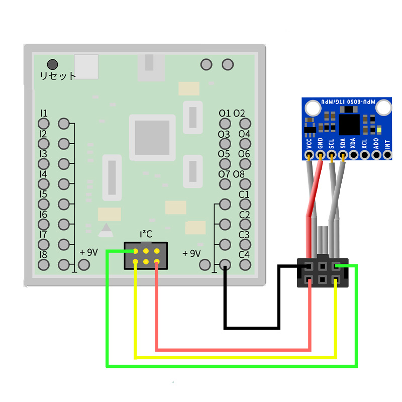
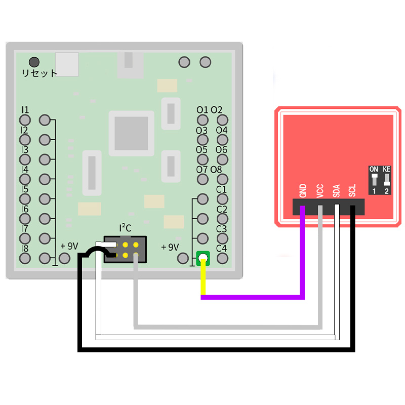
加速度センサー

// MPU-6050-Beispiel-Sketch
//
// Quelle:
// MPU-6050 Short Example Sketch
// By Arduino User JohnChi
// August 17, 2014
// Public Domain

//  == インクルード 必要ファイル読み込み ==
#include <Wire.h> // i2cのライブラリ
#define MPU_ADDR 0x68  // MPU-6050 のアドレス

// 測定値を格納する変数
int16_t AcX,AcY,AcZ,Tmp,GyX,GyY,GyZ;   

void setup() {
  Wire.begin();    // 初期化
  Wire.beginTransmission(MPU_ADDR); // I2Cスレーブにデータ送信開始
  Wire.write(0x6B);                  // I2Cスレーブにデータ送信
  Wire.write(0);                     // I2Cスレーブデバイスにデータ送信
  Wire.endTransmission(true);       // I2Cスレーブデバイスとのデータ送信完了

  // Starte serielle Ausgabe zum PC/seriellen Monitor
  Serial.begin(9600);
  while(!Serial);
}

void loop(){
  // MPU_6050のレジスタンスを読み込み
  Wire.beginTransmission(MPU_ADDR);  // I2Cスレーブにデータ送信開始
  Wire.write(0x3B);                  // I2Cスレーブデバイスにデータ送信
  Wire.endTransmission(false);       // I2Cスレーブデバイスとのデータ送信完了
  Wire.requestFrom(MPU_ADDR,14,true);// 他のI2Cデバイスにデータ要求

  // Wire.read() ---  受信したbyte数を調べる  16bit
  AcX = Wire.read()<<8 | Wire.read();  // x軸の加速度 0x3B (ACCEL_XOUT_H) & 0x3C (ACCEL_XOUT_L)      
  AcY = Wire.read()<<8 | Wire.read();  // y軸の加速度 0x3D (ACCEL_YOUT_H) & 0x3E (ACCEL_YOUT_L)
  AcZ = Wire.read()<<8 | Wire.read();  // z軸の加速度 0x3F (ACCEL_ZOUT_H) & 0x40 (ACCEL_ZOUT_L)
  Tmp = Wire.read()<<8 | Wire.read();  // 温度の読み取り 0x41 (TEMP_OUT_H)   & 0x42 (TEMP_OUT_L)
  GyX = Wire.read()<<8 | Wire.read();  // x軸の角速度 0x43 (GYRO_XOUT_H)  & 0x44 (GYRO_XOUT_L)
  GyY = Wire.read()<<8 | Wire.read();  // y軸の角速度 0x45 (GYRO_YOUT_H)  & 0x46 (GYRO_YOUT_L)
  GyZ = Wire.read()<<8 | Wire.read();  // z軸の角速度 0x47 (GYRO_ZOUT_H)  & 0x48 (GYRO_ZOUT_L)

  // 全ての線形加速度をシリアルモニタへ出力
  Serial.print("AcX = "); Serial.print(AcX);
  Serial.print(" | AcY = "); Serial.print(AcY);
  Serial.print(" | AcZ = "); Serial.print(AcZ);

  // 摂氏
  Serial.print(" | Tmp = "); Serial.print(Tmp/340.00+36.53); 

  // 値をシリアルモニタへ出力
  Serial.print(" | GyX = "); Serial.print(GyX);
  Serial.print(" | GyY = "); Serial.print(GyY);
  Serial.print(" | GyZ = "); Serial.println(GyZ);
  
  delay(500); // 停止
}

サンプルプログラム

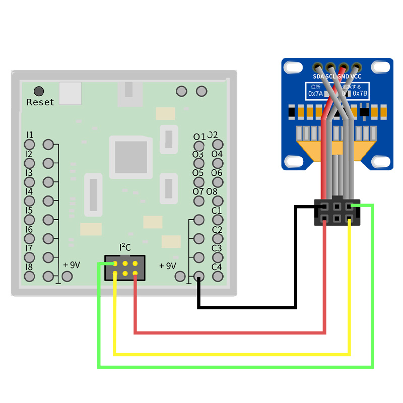
OLED

/**************************************************************************
  This is an example for our Monochrome OLEDs based on SSD1306 drivers

  Pick one up today in the adafruit shop!
  ------> http://www.adafruit.com/category/63_98

  This example is for a 128x32 pixel display using I2C to communicate
  3 pins are required to interface (two I2C and one reset).

  Adafruit invests time and resources providing this open
  source code, please support Adafruit and open-source
  hardware by purchasing products from Adafruit!

  Written by Limor Fried/Ladyada for Adafruit Industries,
  with contributions from the open source community.
  BSD license, check license.txt for more information
  All text above, and the splash screen below must be
  included in any redistribution.
 **************************************************************************/

// == インクルード 必要ファイルの読み込み ==
#include <SPI.h>
#include <Wire.h>
#include <Adafruit_GFX.h>
#include <Adafruit_SSD1306.h>

#define SCREEN_WIDTH 128    // 横の画素数
#define SCREEN_HEIGHT 64    // 縦の画素数
#define OLED_RESET     4    // ピン番号のリセット (Arduinoリセットピンを共有しているなら -1 )
#define SCREEN_ADDRESS 0x3C // アドレス

Adafruit_SSD1306 display(SCREEN_WIDTH, SCREEN_HEIGHT, &Wire, OLED_RESET);

#define NUMFLAKES     10 // 雪の欠片の数
#define LOGO_HEIGHT   16
#define LOGO_WIDTH    16
static const unsigned char PROGMEM logo_bmp[] =   // 配列
{ 0b00000000, 0b11000000,
  0b00000001, 0b11000000,
  0b00000001, 0b11000000,
  0b00000011, 0b11100000,
  0b11110011, 0b11100000,
  0b11111110, 0b11111000,
  0b01111110, 0b11111111,
  0b00110011, 0b10011111,
  0b00011111, 0b11111100,
  0b00001101, 0b01110000,
  0b00011011, 0b10100000,
  0b00111111, 0b11100000,
  0b00111111, 0b11110000,
  0b01111100, 0b11110000,
  0b01110000, 0b01110000,
  0b00000000, 0b00110000
};

void setup() {
  // シリアル通信
  Serial.begin(9600);

  // 初期化
  if (!display.begin(SSD1306_SWITCHCAPVCC, SCREEN_ADDRESS)) {
    Serial.println(F("SSD1306 allocation failed"));
    for (;;); // ループ
  }

  // Adafruit のロゴが2秒間表示される (バッファにあるもの)
  display.display();
  delay(2000);

  // バッファを空にする
  display.clearDisplay();

  // 表示する内容をバッファへと書き込む
  display.drawPixel(10, 10, SSD1306_WHITE);

  // 画面を更新 -- 2秒間
  display.display();
  delay(2000);

  testdrawline();      //  たくさんの線を描画

  testdrawrect();      //  四角を描画 (アウトライン)

  testfillrect();      //  四角を描画 (塗りつぶし)

  testdrawcircle();    // 円を描画(アウトライン)

  testfillcircle();    // 円を描画(塗りつぶし)

  testdrawroundrect(); // 角丸の長方形を描画(アウトライン)

  testfillroundrect(); // 角丸の長方形を描画(塗りつぶし)

  testdrawtriangle();  // 三角形を描画(アウトライン)

  testfilltriangle();  // 三角形を描画(塗りつぶし)

  testdrawchar();      // デフォルトのフォントの文字を描画

  testdrawstyles();    // 様式化された文字を描画

  testscrolltext();    // スクロールテキストを描画

  testdrawbitmap();    // 小さなビットマップ画像を描画


  display.invertDisplay(true); // 白 (1) - 黒(0)が逆転
  delay(1000);                 // 1秒間停止
  display.invertDisplay(false);// 反転を戻す
  delay(1000);                 // 1秒間停止

  // ビットマップをアニメーション化
  testanimate(logo_bmp, LOGO_WIDTH, LOGO_HEIGHT);
}

void loop() {
}

void testdrawline() {  // たくさんの線を描画
  int16_t i;
  display.clearDisplay(); //  バッファを空にする

  /*
     display.drawLine()

      線を描画します
      display.drawLine(x座標の開始点, y座標の開始点, x座標の終了点, y座標の終了点, 線の色)
  */

  //  ==  ディスプレイの横幅までループ ==
  for (i = 0; i < display.width(); i += 4) {
    display.drawLine(0, 0, i, display.height() - 1, SSD1306_WHITE); //  線を描画
    display.display(); // 画面を更新
    delay(1); // 1ミリ秒停止
  }
  //  |||  ディスプレイの縦幅までループ |||
  for (i = 0; i < display.height(); i += 4) {
    display.drawLine(0, 0, display.width() - 1, i, SSD1306_WHITE); // 線を描画
    display.display();   // 画面を更新
    delay(1);   // 1ミリ秒停止
  }
  delay(250);  // 250ミリ秒停止

  display.clearDisplay();  // バッファを空にする

  // == ディスプレイの横幅までループ ==
  for (i = 0; i < display.width(); i += 4) {
    display.drawLine(0, display.height() - 1, i, 0, SSD1306_WHITE); // 線を描画
    display.display();  // 画面を更新
    delay(1); // 1ミリ秒停止
  }

  //  |||  ディスプレイの縦幅までループ  |||
  for (i = display.height() - 1; i >= 0; i -= 4) {
    display.drawLine(0, display.height() - 1, display.width() - 1, i, SSD1306_WHITE); // 線を描画
    display.display(); // 画面を更新
    delay(1);   //  1ミリ秒停止
  }
  delay(250);  // 250ミリ秒停止


  display.clearDisplay();  //  バッファを空にする


  //  ==  ディスプレイの横幅までループ ==
  for (i = display.width() - 1; i >= 0; i -= 4) {
    display.drawLine(display.width() - 1, display.height() - 1, i, 0, SSD1306_WHITE); //  線を描画
    display.display();  //  画面を更新
    delay(1);  // 1ミリ秒停止
  }

  // |||  ディスプレイの縦幅までループ  |||
  for (i = display.height() - 1; i >= 0; i -= 4) {
    display.drawLine(display.width() - 1, display.height() - 1, 0, i, SSD1306_WHITE); //  線を描画
    display.display();    //   画面を更新
    delay(1);     //    1ミリ秒停止
  }


  delay(250);     //   250ミリ秒間停止


  display.clearDisplay();     //  バッファを空にする

  //  |||  ディスプレイの縦幅までループ  |||
  for (i = 0; i < display.height(); i += 4) {
    display.drawLine(display.width() - 1, 0, 0, i, SSD1306_WHITE); //  線を描画
    display.display();  // 画面を更新
    delay(1);   //  1ミリ秒停止
  }
  //  ==  ディスプレイの横幅までループ  ===
  for (i = 0; i < display.width(); i += 4) {
    display.drawLine(display.width() - 1, 0, i, display.height() - 1, SSD1306_WHITE); //  線を描画
    display.display();   //   画面を更新
    delay(1);   // 1ミリ秒停止
  }

  delay(2000); //   2秒間停止
}


void testdrawrect(void) {
  display.clearDisplay(); //  バッファを空にする

  /*
      display.drawRect()

      四角を描画します  (アウトライン)
      display.drawRect(x座標のの開始点, y座標の開始点, 幅, 高さ, 線の色)
  */

  //  == ディスプレイの縦幅 / 2 まで  ループ ==
  for (int16_t i = 0; i < display.height() / 2; i += 2) {
    display.drawRect(i, i, display.width() - 2 * i, display.height() - 2 * i, SSD1306_WHITE); // ループするたびに内側へ
    display.display(); //  画面を更新
    delay(1);  // 1ミリ秒停止
  }

  delay(2000);   //  2秒間停止
}

void testfillrect(void) {
  display.clearDisplay();   //   バッファを空にする1

  /*
     display.fillRect()

     四角を描画 (塗りつぶしあり)
     display.ffillRect(x座標のの開始点, y座標の開始点, 幅, 高さ, 線の色)
  */

  //  == ディスプレイの縦幅 / 2  までループ ==
  for (int16_t i = 0; i < display.height() / 2; i += 3) {
    display.fillRect(i, i, display.width() - i * 2, display.height() - i * 2, SSD1306_INVERSE); //  四角を描画
    display.display(); // 画面を更新
    delay(1); // 1ミリ秒停止
  }

  delay(2000); // 2秒間停止
}

void testdrawcircle(void) {
  display.clearDisplay();//  バッファを空にする

  /*
      display.drawCircle()

     円を描画 (アウトライン)
     display.drawCircle(円の中心のx座標, 円の中心のy座標, 円の半径, 線の色)
  */

  //  ==  (横幅,縦幅)の大きい方の値 / 2  まで ループ ==
  for (int16_t i = 0; i < max(display.width(), display.height()) / 2; i += 2) {
    display.drawCircle(display.width() / 2, display.height() / 2, i, SSD1306_WHITE); //  円を描画
    display.display();  //  画面を更新
    delay(1);  //  1ミリ秒停止
  }

  delay(2000);   //  2秒間停止
}

void testfillcircle(void) {
  display.clearDisplay();  //  バッファを空にする

  /*
     display.fillCircle()

     円を描画 (塗りつぶしあり)
     display.fillCircle(円の中心x座標, 円の中心y座標, 円の半径, 線の色)
  */

  // ループ
  for (int16_t i = max(display.width(), display.height()) / 2; i > 0; i -= 3) {
    // INVERSEカラーが使用されるため、円は白/黒を交互に表示します
    display.fillCircle(display.width() / 2, display.height() / 2, i, SSD1306_INVERSE);
    display.display(); // 画像を更新
    delay(1);  // 1ミリ秒停止
  }

  delay(2000);   // 2秒停止
}

void testdrawroundrect(void) {
  display.clearDisplay();  //バッファを空にする

  /*
       display.drawRountRect()

      四角を描画(塗りつぶしなし)
      display.drawRect(左上x, 左上y, 幅, 高さ, 線の色)
  */

  // ループ
  for (int16_t i = 0; i < display.height() / 2 - 2; i += 2) {
    display.drawRoundRect(i, i, display.width() - 2 * i, display.height() - 2 * i,
                          display.height() / 4, SSD1306_WHITE);
    display.display();  // 画面を更新
    delay(1);  // 1ミリ秒停止
  }

  delay(2000);  // 2秒間停止
}

void testfillroundrect(void) {
  display.clearDisplay();  // バッファを空にする

  for (int16_t i = 0; i < display.height() / 2 - 2; i += 2) {
    //  角丸の四角を描画
    display.fillRoundRect(i, i, display.width() - 2 * i, display.height() - 2 * i,
                          display.height() / 4, SSD1306_INVERSE);
    display.display();
    delay(1);
  }

  delay(2000);
}

void testdrawtriangle(void) {
  display.clearDisplay();  //  バッファを空にする
  //  ループ
  for (int16_t i = 0; i < max(display.width(), display.height()) / 2; i += 5) {
    // 三角形を描画
    display.drawTriangle(
      display.width() / 2  , display.height() / 2 - i,
      display.width() / 2 - i, display.height() / 2 + i,
      display.width() / 2 + i, display.height() / 2 + i, SSD1306_WHITE);
    display.display();
    delay(1);
  }

  delay(2000);
}

void testfilltriangle(void) {
  display.clearDisplay();   //  バッファを空にする

  for (int16_t i = max(display.width(), display.height()) / 2; i > 0; i -= 5) {
    // T三角形を描画(塗りつぶしあり)
    display.fillTriangle(
      display.width() / 2  , display.height() / 2 - i,
      display.width() / 2 - i, display.height() / 2 + i,
      display.width() / 2 + i, display.height() / 2 + i, SSD1306_INVERSE);
    display.display();
    delay(1);
  }

  delay(2000); // 2秒間停止
}

void testdrawchar(void) {
  display.clearDisplay();   //   バッファを空にする

  display.setTextSize(1);      // 文字サイズの設定
  display.setTextColor(SSD1306_WHITE); // 文字の色の設定
  display.setCursor(0, 0);     // カーソルの位置の設定
  display.cp437(true);         // Use full 256 char 'Code Page 437' font

  //  ループ
  for (int16_t i = 0; i < 256; i++) {
    if (i == '\n') display.write(' ');
    else          display.write(i);
  }

  display.display();   //  画面の更新
  delay(2000);    //  2秒間停止
}

void testdrawstyles(void) {
  display.clearDisplay();    //  バッファを空にする

  display.setTextSize(1);             //  テキストサイズの設定
  display.setTextColor(SSD1306_WHITE);        // 文字色の設定
  display.setCursor(0, 0);            // カーソル位置の設定
  display.println(F("Hello, world!")); // Flush ram から直接読む

  display.setTextColor(SSD1306_BLACK, SSD1306_WHITE); // 色の設定
  display.println(3.141592); // 文字の出力

  display.setTextSize(2);             // 文字サイズの設定
  display.setTextColor(SSD1306_WHITE);   // 文字の色の設定
  display.print(F("0x"));       //  文字の出力
  display.println(0xDEADBEEF, HEX);   //  文字の出力

  display.display();  //  画面の更新
  delay(2000);  //  2秒間停止
}

void testscrolltext(void) {
  display.clearDisplay();  //  バッファを空にする

  display.setTextSize(2); // テキストサイズの設定
  display.setTextColor(SSD1306_WHITE);  //  文字の色
  display.setCursor(10, 0);  //  カーソルの位置
  display.println(F("scroll"));  // Flush ram から直接読む
  display.display();      // 画面の更新
  delay(100);     // 100ミリ秒停止

  //  ==  スクロール  ==
  display.startscrollright(0x00, 0x0F);  // 右スクロール
  delay(2000);
  display.stopscroll();    //  スクロールの停止
  delay(1000);
  display.startscrollleft(0x00, 0x0F);  //  左スクロール
  delay(2000);
  display.stopscroll(); // スクロールの停止
  delay(1000);
  display.startscrolldiagleft(0x00, 0x07);  // 上へスクロール
  delay(2000);
  display.startscrolldiagright(0x00, 0x07); //  下へスクロール
  delay(2000);
  display.stopscroll();  //  スクロールの停止
  delay(1000);
  display.display();      // 画面の更新
}

void testdrawbitmap(void) {
  display.clearDisplay();  //  バッファを空にする

  display.drawBitmap(
    (display.width()  - LOGO_WIDTH ) ,
    (display.height() - LOGO_HEIGHT),
    logo_bmp, LOGO_WIDTH, LOGO_HEIGHT, 1);
  display.display();
  delay(1000);
}

#define XPOS   0
#define YPOS   1
#define DELTAY 2

void testanimate(const uint8_t *bitmap, uint8_t w, uint8_t h) {
  int8_t f, icons[NUMFLAKES][3];
  display.clearDisplay();   //   バッファを空にする

  //  雪の位置を初期化
  for (f = 0; f < NUMFLAKES; f++) {
    icons[f][XPOS]   = random(1 - LOGO_WIDTH, display.width());
    icons[f][YPOS]   = -LOGO_HEIGHT;
    icons[f][DELTAY] = random(1, 6);
    Serial.print(F("x: "));
    Serial.print(icons[f][XPOS], DEC);
    Serial.print(F(" y: "));
    Serial.print(icons[f][YPOS], DEC);
    Serial.print(F(" dy: "));
    Serial.println(icons[f][DELTAY], DEC);
  }

  for (;;) { //  ループ
    display.clearDisplay(); // バッファを空にする
    //  ループ
    for (f = 0; f < NUMFLAKES; f++) {
      display.drawBitmap(icons[f][XPOS], icons[f][YPOS], bitmap, w, h, SSD1306_WHITE);
    }

    display.display(); // 画面の更新
    delay(200);        // 200ミリ秒停止

    /*
        display.drawBitmap(x,y,bitmap,rotation,flip)

       画面上にバイト配列であるビットマップを表示します
       display.drawBitmap(x座標,y座標,bitmap,オプション(ビットマップの回転),オプション(ビットマップの反転))
                                            ↑NOROT, ROTCCW, ROT180, ROTCW   ↑NOFLIP, FLIPH, FLIPV, FLIPVH
    */

    // 雪の描画
    //  ループ
    for (f = 0; f < NUMFLAKES; f++) {
      icons[f][YPOS] += icons[f][DELTAY];
      //  雪が画面の下部から外れている場合
      if (icons[f][YPOS] >= display.height()) {
        //上部から少し離れたランダムな位置に再初期化します
        icons[f][XPOS]   = random(1 - LOGO_WIDTH, display.width());
        icons[f][YPOS]   = -LOGO_HEIGHT;
        icons[f][DELTAY] = random(1, 6);
      }
    }
  }
}

サンプルプログラム

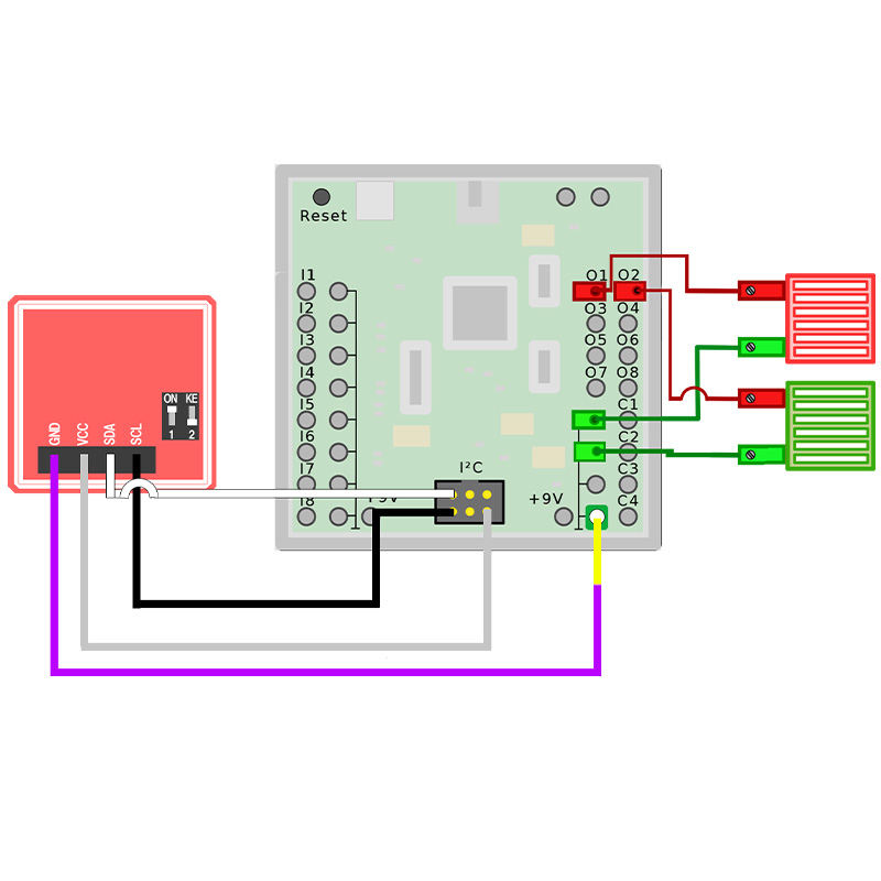
NFC

//  == インクルード 必要ファイル読み込み ==
#include <Wire.h>
#include "Adafruit_PN532.h"
#include <FtduinoSimple.h>

#define PN532_IRQ   (0)
#define PN532_RESET (0)

Adafruit_PN532 nfc(PN532_IRQ, PN532_RESET);

void setup(void) {
  Serial.begin(115200);

  // USBを最大3秒待つ
  uint32_t to = millis();
  while ((!Serial) && ((millis() - to) < 3000))
    delay(10);

  nfc.begin();

  //  ファームウェアのバージョン情報を格納する変数
  uint32_t versiondata = nfc.getFirmwareVersion();
  // NFCリーダー(PN532)が見つからないとき
  if (! versiondata) {
    Serial.print("PN532がありません");
    while (1); //  停止
  }

  // 見つかった場合
  //  ファームウェアのバージョン情報を表示
  Serial.print("PN532が見つかりました"); Serial.println((versiondata >> 24) & 0xFF, HEX);
  Serial.print("ファームウェアのバージョン : "); Serial.print((versiondata >> 16) & 0xFF, DEC);
  Serial.print('.'); Serial.println((versiondata >> 8) & 0xFF, DEC);

  // RFIDタグを読みとるように構成
  nfc.SAMConfig();
  //  シリアルモニタへ表示
  Serial.println("待機中 ...");
  // 内部LED ON
  pinMode(LED_BUILTIN, OUTPUT);
  digitalWrite(LED_BUILTIN, HIGH);
}

void loop(void) {
  //  UID Value を格納する配列
  static uint8_t registered_uid[4];
  //  カードの入力がまだないかの状態を表す変数
  static bool registered = false;
  //  返された UID を格納するためのバッファ
  uint8_t uid[] = { 0, 0, 0, 0, 0, 0, 0 };
  //  UIDの長さ (byte数) (ISO14443Aカードタイプに応じて4または7バイト)
  uint8_t uidLength;

  //  カードの入力を待つ
  //  'uid'には UID Value 'uidLength'には UID Length が入る
  if (nfc.readPassiveTargetID(PN532_MIFARE_ISO14443A, uid, &uidLength, 100)) {
    //  カード状態を表示
    Serial.println("ISO14443Aカードが見つかりました");
    Serial.print("  UID Length: "); Serial.print(uidLength, DEC); Serial.println(" bytes");
    Serial.print("  UID Value: ");  nfc.PrintHex(uid, uidLength);
    Serial.println("");

    if (uidLength == 4) {
      Serial.println("-- Mifare Classicカードです --");

      // 最初のカードなら受け入れる
      if (!registered) {
        Serial.println("カードを登録");
        memcpy(registered_uid, uid, uidLength);
        digitalWrite(LED_BUILTIN, LOW); // 内部LED 消灯
        registered = true; // 状態を変更
      } else {
        if (memcmp(registered_uid, uid, uidLength) == 0) {
          Serial.println("== 受け付けました ==");
          // O1のLEDを点灯
          ftduino.output_set(Ftduino::O1, Ftduino::HI);
          ftduino.output_set(Ftduino::O2, Ftduino::LO);
        } else {
          // O2のLEDを点灯
          Serial.println("== カードが拒否されました ==");
          ftduino.output_set(Ftduino::O1, Ftduino::LO);
          ftduino.output_set(Ftduino::O2, Ftduino::HI);
        }
      }
    }
  } else {
    //  カードがない時は どちらのLEDもOFF
    ftduino.output_set(Ftduino::O1, Ftduino::LO);
    ftduino.output_set(Ftduino::O2, Ftduino::LO);
  }
}

=============== // Adafruit_PN532.cpp
/**************************************************************************/
/*!
    @file     Adafruit_PN532.cpp
    @author   Adafruit Industries
    @license  BSD (see license.txt)
    
          Driver for NXP's PN532 NFC/13.56MHz RFID Transceiver

          This is a library for the Adafruit PN532 NFC/RFID breakout boards
          This library works with the Adafruit NFC breakout
          ----> https://www.adafruit.com/products/364

          Check out the links above for our tutorials and wiring diagrams
          These chips use SPI or I2C to communicate.

          https://www.nxp.com/docs/en/user-guide/141520.pdf

          Adafruit invests time and resources providing this open source code,
          please support Adafruit and open-source hardware by purchasing
          products from Adafruit!

    @section  HISTORY

    v2.1 - Added NTAG2xx helper functions

    v2.0 - Refactored to add I2C support from Adafruit_NFCShield_I2C library.

    v1.4 - Added setPassiveActivationRetries()

    v1.2 - Added writeGPIO()
         - Added readGPIO()

    v1.1 - Changed readPassiveTargetID() to handle multiple UID sizes
         - Added the following helper functions for text display
             static void PrintHex(const byte * data, const uint32_t numBytes)
             static void PrintHexChar(const byte * pbtData, const uint32_t
   numBytes)
         - Added the following Mifare Classic functions:
             bool mifareclassic_IsFirstBlock (uint32_t uiBlock)
             bool mifareclassic_IsTrailerBlock (uint32_t uiBlock)
             uint8_t mifareclassic_AuthenticateBlock (uint8_t * uid, uint8_t
   uidLen, uint32_t blockNumber, uint8_t keyNumber, uint8_t * keyData) uint8_t
   mifareclassic_ReadDataBlock (uint8_t blockNumber, uint8_t * data) uint8_t
   mifareclassic_WriteDataBlock (uint8_t blockNumber, uint8_t * data)
         - Added the following Mifare Ultalight functions:
             uint8_t mifareultralight_ReadPage (uint8_t page, uint8_t * buffer)
*/
/**************************************************************************/

#include "Arduino.h"

#include <Wire.h>
#ifdef __SAM3X8E__ // arduino due
#define WIRE Wire1
#else
#define WIRE Wire
#endif

#include <SPI.h>

#include "Adafruit_PN532.h"

byte pn532ack[] = {0x00, 0x00, 0xFF, 0x00, 0xFF, 0x00};
byte pn532response_firmwarevers[] = {0x00, 0x00, 0xFF, 0x06, 0xFA, 0xD5};

// Uncomment these lines to enable debug output for PN532(SPI) and/or MIFARE
// related code

// #define PN532DEBUG
// #define MIFAREDEBUG

// If using Native Port on Arduino Zero or Due define as SerialUSB
#define PN532DEBUGPRINT Serial
//#define PN532DEBUGPRINT SerialUSB

#define PN532_PACKBUFFSIZ 64
byte pn532_packetbuffer[PN532_PACKBUFFSIZ];

#ifndef _BV
#define _BV(bit) (1 << (bit))
#endif

/**************************************************************************/
/*!
    @brief  Sends a single byte via I2C

    @param  x    The byte to send
*/
/**************************************************************************/
static inline void i2c_send(uint8_t x) {
#if ARDUINO >= 100
  WIRE.write((uint8_t)x);
#else
  WIRE.send(x);
#endif
}

/**************************************************************************/
/*!
    @brief  Reads a single byte via I2C
*/
/**************************************************************************/
static inline uint8_t i2c_recv(void) {
#if ARDUINO >= 100
  return WIRE.read();
#else
  return WIRE.receive();
#endif
}

/**************************************************************************/
/*!
    @brief  Instantiates a new PN532 class using software SPI.

    @param  clk       SPI clock pin (SCK)
    @param  miso      SPI MISO pin
    @param  mosi      SPI MOSI pin
    @param  ss        SPI chip select pin (CS/SSEL)
*/
/**************************************************************************/
Adafruit_PN532::Adafruit_PN532(uint8_t clk, uint8_t miso, uint8_t mosi,
                               uint8_t ss) {
  spi_dev = new Adafruit_SPIDevice(ss, clk, miso, mosi, 1000000,
                                   SPI_BITORDER_LSBFIRST, SPI_MODE0);
}

/**************************************************************************/
/*!
    @brief  Instantiates a new PN532 class using I2C.

    @param  irq       Location of the IRQ pin
    @param  reset     Location of the RSTPD_N pin
*/
/**************************************************************************/
Adafruit_PN532::Adafruit_PN532(uint8_t irq, uint8_t reset)
    : _irq(irq), _reset(reset) {
  pinMode(_irq, INPUT);
  pinMode(_reset, OUTPUT);
}

/**************************************************************************/
/*!
    @brief  Instantiates a new PN532 class using hardware SPI.

    @param  ss        SPI chip select pin (CS/SSEL)
*/
/**************************************************************************/
Adafruit_PN532::Adafruit_PN532(uint8_t ss) {
  spi_dev =
      new Adafruit_SPIDevice(ss, 1000000, SPI_BITORDER_LSBFIRST, SPI_MODE0);
}

/**************************************************************************/
/*!
    @brief  Setups the HW
*/
/**************************************************************************/
void Adafruit_PN532::begin() {
  if (spi_dev != NULL) {
    // SPI initialization
    spi_dev->begin();

    // not exactly sure why but we have to send a dummy command to get synced up
    pn532_packetbuffer[0] = PN532_COMMAND_GETFIRMWAREVERSION;
    sendCommandCheckAck(pn532_packetbuffer, 1);
    // ignore response!
  } else {
    // I2C initialization.
    WIRE.begin();
    if(_reset) {
      // Reset the PN532
      digitalWrite(_reset, HIGH);
      digitalWrite(_reset, LOW);
      delay(400);
      digitalWrite(_reset, HIGH);
      delay(
        10); // Small delay required before taking other actions after reset.
             // See timing diagram on page 209 of the datasheet, section 12.23.
    }
  }
}

/**************************************************************************/
/*!
    @brief  Prints a hexadecimal value in plain characters

    @param  data      Pointer to the byte data
    @param  numBytes  Data length in bytes
*/
/**************************************************************************/
void Adafruit_PN532::PrintHex(const byte *data, const uint32_t numBytes) {
  uint32_t szPos;
  for (szPos = 0; szPos < numBytes; szPos++) {
    PN532DEBUGPRINT.print(F("0x"));
    // Append leading 0 for small values
    if (data[szPos] <= 0xF)
      PN532DEBUGPRINT.print(F("0"));
    PN532DEBUGPRINT.print(data[szPos] & 0xff, HEX);
    if ((numBytes > 1) && (szPos != numBytes - 1)) {
      PN532DEBUGPRINT.print(F(" "));
    }
  }
  PN532DEBUGPRINT.println();
}

/**************************************************************************/
/*!
    @brief  Prints a hexadecimal value in plain characters, along with
            the char equivalents in the following format

            00 00 00 00 00 00  ......

    @param  data      Pointer to the byte data
    @param  numBytes  Data length in bytes
*/
/**************************************************************************/
void Adafruit_PN532::PrintHexChar(const byte *data, const uint32_t numBytes) {
  uint32_t szPos;
  for (szPos = 0; szPos < numBytes; szPos++) {
    // Append leading 0 for small values
    if (data[szPos] <= 0xF)
      PN532DEBUGPRINT.print(F("0"));
    PN532DEBUGPRINT.print(data[szPos], HEX);
    if ((numBytes > 1) && (szPos != numBytes - 1)) {
      PN532DEBUGPRINT.print(F(" "));
    }
  }
  PN532DEBUGPRINT.print(F("  "));
  for (szPos = 0; szPos < numBytes; szPos++) {
    if (data[szPos] <= 0x1F)
      PN532DEBUGPRINT.print(F("."));
    else
      PN532DEBUGPRINT.print((char)data[szPos]);
  }
  PN532DEBUGPRINT.println();
}

/**************************************************************************/
/*!
    @brief  Checks the firmware version of the PN5xx chip

    @returns  The chip's firmware version and ID
*/
/**************************************************************************/
uint32_t Adafruit_PN532::getFirmwareVersion(void) {
  uint32_t response;

  pn532_packetbuffer[0] = PN532_COMMAND_GETFIRMWAREVERSION;

  if (!sendCommandCheckAck(pn532_packetbuffer, 1)) {
    return 0;
  }

  // read data packet
  readdata(pn532_packetbuffer, 12);

  // check some basic stuff
  if (0 != memcmp((char *)pn532_packetbuffer,
                  (char *)pn532response_firmwarevers, 6)) {
#ifdef PN532DEBUG
    PN532DEBUGPRINT.println(F("Firmware doesn't match!"));
#endif
    return 0;
  }

  int offset = 7;
  response = pn532_packetbuffer[offset++];
  response <<= 8;
  response |= pn532_packetbuffer[offset++];
  response <<= 8;
  response |= pn532_packetbuffer[offset++];
  response <<= 8;
  response |= pn532_packetbuffer[offset++];

  return response;
}

/**************************************************************************/
/*!
    @brief  Sends a command and waits a specified period for the ACK

    @param  cmd       Pointer to the command buffer
    @param  cmdlen    The size of the command in bytes
    @param  timeout   timeout before giving up

    @returns  1 if everything is OK, 0 if timeout occured before an
              ACK was recieved
*/
/**************************************************************************/
// default timeout of one second
bool Adafruit_PN532::sendCommandCheckAck(uint8_t *cmd, uint8_t cmdlen,
                                         uint16_t timeout) {
  // uint16_t timer = 0;

  // write the command
  writecommand(cmd, cmdlen);

  // Wait for chip to say its ready!
  if (!waitready(timeout)) {
    return false;
  }
  
#ifdef PN532DEBUG
  if (spi_dev == NULL) {
    PN532DEBUGPRINT.println(F("IRQ received"));
  }
#endif

  // read acknowledgement
  if (!readack()) {
#ifdef PN532DEBUG
    PN532DEBUGPRINT.println(F("No ACK frame received!"));
#endif
    return false;
  }

  // For SPI only wait for the chip to be ready again.
  // This is unnecessary with I2C.
  if (spi_dev != NULL) {
    if (!waitready(timeout)) {
      return false;
    }
  }

  return true; // ack'd command
}

/**************************************************************************/
/*!
    Writes an 8-bit value that sets the state of the PN532's GPIO pins

    @warning This function is provided exclusively for board testing and
             is dangerous since it will throw an error if any pin other
             than the ones marked "Can be used as GPIO" are modified!  All
             pins that can not be used as GPIO should ALWAYS be left high
             (value = 1) or the system will become unstable and a HW reset
             will be required to recover the PN532.

             pinState[0]  = P30     Can be used as GPIO
             pinState[1]  = P31     Can be used as GPIO
             pinState[2]  = P32     *** RESERVED (Must be 1!) ***
             pinState[3]  = P33     Can be used as GPIO
             pinState[4]  = P34     *** RESERVED (Must be 1!) ***
             pinState[5]  = P35     Can be used as GPIO

    @returns 1 if everything executed properly, 0 for an error
*/
/**************************************************************************/
bool Adafruit_PN532::writeGPIO(uint8_t pinstate) {
  // uint8_t errorbit;

  // Make sure pinstate does not try to toggle P32 or P34
  pinstate |= (1 << PN532_GPIO_P32) | (1 << PN532_GPIO_P34);

  // Fill command buffer
  pn532_packetbuffer[0] = PN532_COMMAND_WRITEGPIO;
  pn532_packetbuffer[1] = PN532_GPIO_VALIDATIONBIT | pinstate; // P3 Pins
  pn532_packetbuffer[2] = 0x00; // P7 GPIO Pins (not used ... taken by SPI)

#ifdef PN532DEBUG
  PN532DEBUGPRINT.print(F("Writing P3 GPIO: "));
  PN532DEBUGPRINT.println(pn532_packetbuffer[1], HEX);
#endif

  // Send the WRITEGPIO command (0x0E)
  if (!sendCommandCheckAck(pn532_packetbuffer, 3))
    return 0x0;

  // Read response packet (00 FF PLEN PLENCHECKSUM D5 CMD+1(0x0F) DATACHECKSUM
  // 00)
  readdata(pn532_packetbuffer, 8);

#ifdef PN532DEBUG
  PN532DEBUGPRINT.print(F("Received: "));
  PrintHex(pn532_packetbuffer, 8);
  PN532DEBUGPRINT.println();
#endif

  int offset = 6;
  return (pn532_packetbuffer[offset] == 0x0F);
}

/**************************************************************************/
/*!
    Reads the state of the PN532's GPIO pins

    @returns An 8-bit value containing the pin state where:

             pinState[0]  = P30
             pinState[1]  = P31
             pinState[2]  = P32
             pinState[3]  = P33
             pinState[4]  = P34
             pinState[5]  = P35
*/
/**************************************************************************/
uint8_t Adafruit_PN532::readGPIO(void) {
  pn532_packetbuffer[0] = PN532_COMMAND_READGPIO;

  // Send the READGPIO command (0x0C)
  if (!sendCommandCheckAck(pn532_packetbuffer, 1))
    return 0x0;

  // Read response packet (00 FF PLEN PLENCHECKSUM D5 CMD+1(0x0D) P3 P7 IO1
  // DATACHECKSUM 00)
  readdata(pn532_packetbuffer, 11);

  /* READGPIO response should be in the following format:

    byte            Description
    -------------   ------------------------------------------
    b0..5           Frame header and preamble (with I2C there is an extra 0x00)
    b6              P3 GPIO Pins
    b7              P7 GPIO Pins (not used ... taken by SPI)
    b8              Interface Mode Pins (not used ... bus select pins)
    b9..10          checksum */

  int p3offset = 7;

#ifdef PN532DEBUG
  PN532DEBUGPRINT.print(F("Received: "));
  PrintHex(pn532_packetbuffer, 11);
  PN532DEBUGPRINT.println();
  PN532DEBUGPRINT.print(F("P3 GPIO: 0x"));
  PN532DEBUGPRINT.println(pn532_packetbuffer[p3offset], HEX);
  PN532DEBUGPRINT.print(F("P7 GPIO: 0x"));
  PN532DEBUGPRINT.println(pn532_packetbuffer[p3offset + 1], HEX);
  PN532DEBUGPRINT.print(F("IO GPIO: 0x"));
  PN532DEBUGPRINT.println(pn532_packetbuffer[p3offset + 2], HEX);
  // Note: You can use the IO GPIO value to detect the serial bus being used
  switch (pn532_packetbuffer[p3offset + 2]) {
  case 0x00: // Using UART
    PN532DEBUGPRINT.println(F("Using UART (IO = 0x00)"));
    break;
  case 0x01: // Using I2C
    PN532DEBUGPRINT.println(F("Using I2C (IO = 0x01)"));
    break;
  case 0x02: // Using SPI
    PN532DEBUGPRINT.println(F("Using SPI (IO = 0x02)"));
    break;
  }
#endif

  return pn532_packetbuffer[p3offset];
}

/**************************************************************************/
/*!
    @brief  Configures the SAM (Secure Access Module)
*/
/**************************************************************************/
bool Adafruit_PN532::SAMConfig(void) {
  pn532_packetbuffer[0] = PN532_COMMAND_SAMCONFIGURATION;
  pn532_packetbuffer[1] = 0x01; // normal mode;
  pn532_packetbuffer[2] = 0x14; // timeout 50ms * 20 = 1 second
  pn532_packetbuffer[3] = 0x01; // use IRQ pin!

  if (!sendCommandCheckAck(pn532_packetbuffer, 4))
    return false;

  // read data packet
  readdata(pn532_packetbuffer, 8);

  int offset = 6;
  return (pn532_packetbuffer[offset] == 0x15);
}

/**************************************************************************/
/*!
    Sets the MxRtyPassiveActivation byte of the RFConfiguration register

    @param  maxRetries    0xFF to wait forever, 0x00..0xFE to timeout
                          after mxRetries

    @returns 1 if everything executed properly, 0 for an error
*/
/**************************************************************************/
bool Adafruit_PN532::setPassiveActivationRetries(uint8_t maxRetries) {
  pn532_packetbuffer[0] = PN532_COMMAND_RFCONFIGURATION;
  pn532_packetbuffer[1] = 5;    // Config item 5 (MaxRetries)
  pn532_packetbuffer[2] = 0xFF; // MxRtyATR (default = 0xFF)
  pn532_packetbuffer[3] = 0x01; // MxRtyPSL (default = 0x01)
  pn532_packetbuffer[4] = maxRetries;

#ifdef MIFAREDEBUG
  PN532DEBUGPRINT.print(F("Setting MxRtyPassiveActivation to "));
  PN532DEBUGPRINT.print(maxRetries, DEC);
  PN532DEBUGPRINT.println(F(" "));
#endif

  if (!sendCommandCheckAck(pn532_packetbuffer, 5))
    return 0x0; // no ACK

  return 1;
}

/***** ISO14443A Commands ******/

/**************************************************************************/
/*!
    Waits for an ISO14443A target to enter the field

    @param  cardBaudRate  Baud rate of the card
    @param  uid           Pointer to the array that will be populated
                          with the card's UID (up to 7 bytes)
    @param  uidLength     Pointer to the variable that will hold the
                          length of the card's UID.

    @returns 1 if everything executed properly, 0 for an error
*/
/**************************************************************************/
bool Adafruit_PN532::readPassiveTargetID(uint8_t cardbaudrate, uint8_t *uid,
                                         uint8_t *uidLength, uint16_t timeout) {
  pn532_packetbuffer[0] = PN532_COMMAND_INLISTPASSIVETARGET;
  pn532_packetbuffer[1] = 1; // max 1 cards at once (we can set this to 2 later)
  pn532_packetbuffer[2] = cardbaudrate;

  // TH: this will always ack (at least for i2c) and will _not_ timeout if no cards are present
  if (!sendCommandCheckAck(pn532_packetbuffer, 3, timeout)) {
#ifdef PN532DEBUG
    PN532DEBUGPRINT.println(F("No card(s) read"));
#endif
    return 0x0; // no cards read
  }

  // wait for a card to enter the field (only possible with I2C)
  if (spi_dev == NULL) {
#ifdef PN532DEBUG
    PN532DEBUGPRINT.println(F("Waiting for IRQ (indicates card presence)"));
#endif
    if (!waitready(timeout)) {
#ifdef PN532DEBUG
      PN532DEBUGPRINT.println(F("IRQ Timeout"));
#endif
      return 0x0;
    }    
  }

  // read data packet
  readdata(pn532_packetbuffer, 20);
  // check some basic stuff

  /* ISO14443A card response should be in the following format:

    byte            Description
    -------------   ------------------------------------------
    b0..6           Frame header and preamble
    b7              Tags Found
    b8              Tag Number (only one used in this example)
    b9..10          SENS_RES
    b11             SEL_RES
    b12             NFCID Length
    b13..NFCIDLen   NFCID                                      */

#ifdef MIFAREDEBUG
  PN532DEBUGPRINT.print(F("Found "));
  PN532DEBUGPRINT.print(pn532_packetbuffer[7], DEC);
  PN532DEBUGPRINT.println(F(" tags"));
#endif
  if (pn532_packetbuffer[7] != 1)
    return 0;

  uint16_t sens_res = pn532_packetbuffer[9];
  sens_res <<= 8;
  sens_res |= pn532_packetbuffer[10];
#ifdef MIFAREDEBUG
  PN532DEBUGPRINT.print(F("ATQA: 0x"));
  PN532DEBUGPRINT.println(sens_res, HEX);
  PN532DEBUGPRINT.print(F("SAK: 0x"));
  PN532DEBUGPRINT.println(pn532_packetbuffer[11], HEX);
#endif

  /* Card appears to be Mifare Classic */
  *uidLength = pn532_packetbuffer[12];
#ifdef MIFAREDEBUG
  PN532DEBUGPRINT.print(F("UID:"));
#endif
  for (uint8_t i = 0; i < pn532_packetbuffer[12]; i++) {
    uid[i] = pn532_packetbuffer[13 + i];
#ifdef MIFAREDEBUG
    PN532DEBUGPRINT.print(F(" 0x"));
    PN532DEBUGPRINT.print(uid[i], HEX);
#endif
  }
#ifdef MIFAREDEBUG
  PN532DEBUGPRINT.println();
#endif

  return 1;
}

/**************************************************************************/
/*!
    @brief  Exchanges an APDU with the currently inlisted peer

    @param  send            Pointer to data to send
    @param  sendLength      Length of the data to send
    @param  response        Pointer to response data
    @param  responseLength  Pointer to the response data length
*/
/**************************************************************************/
bool Adafruit_PN532::inDataExchange(uint8_t *send, uint8_t sendLength,
                                    uint8_t *response,
                                    uint8_t *responseLength) {
  if (sendLength > PN532_PACKBUFFSIZ - 2) {
#ifdef PN532DEBUG
    PN532DEBUGPRINT.println(F("APDU length too long for packet buffer"));
#endif
    return false;
  }
  uint8_t i;

  pn532_packetbuffer[0] = 0x40; // PN532_COMMAND_INDATAEXCHANGE;
  pn532_packetbuffer[1] = _inListedTag;
  for (i = 0; i < sendLength; ++i) {
    pn532_packetbuffer[i + 2] = send[i];
  }

  if (!sendCommandCheckAck(pn532_packetbuffer, sendLength + 2, 1000)) {
#ifdef PN532DEBUG
    PN532DEBUGPRINT.println(F("Could not send APDU"));
#endif
    return false;
  }

  if (!waitready(1000)) {
#ifdef PN532DEBUG
    PN532DEBUGPRINT.println(F("Response never received for APDU..."));
#endif
    return false;
  }

  readdata(pn532_packetbuffer, sizeof(pn532_packetbuffer));

  if (pn532_packetbuffer[0] == 0 && pn532_packetbuffer[1] == 0 &&
      pn532_packetbuffer[2] == 0xff) {
    uint8_t length = pn532_packetbuffer[3];
    if (pn532_packetbuffer[4] != (uint8_t)(~length + 1)) {
#ifdef PN532DEBUG
      PN532DEBUGPRINT.println(F("Length check invalid"));
      PN532DEBUGPRINT.println(length, HEX);
      PN532DEBUGPRINT.println((~length) + 1, HEX);
#endif
      return false;
    }
    if (pn532_packetbuffer[5] == PN532_PN532TOHOST &&
        pn532_packetbuffer[6] == PN532_RESPONSE_INDATAEXCHANGE) {
      if ((pn532_packetbuffer[7] & 0x3f) != 0) {
#ifdef PN532DEBUG
        PN532DEBUGPRINT.println(F("Status code indicates an error"));
#endif
        return false;
      }

      length -= 3;

      if (length > *responseLength) {
        length = *responseLength; // silent truncation...
      }

      for (i = 0; i < length; ++i) {
        response[i] = pn532_packetbuffer[8 + i];
      }
      *responseLength = length;

      return true;
    } else {
      PN532DEBUGPRINT.print(F("Don't know how to handle this command: "));
      PN532DEBUGPRINT.println(pn532_packetbuffer[6], HEX);
      return false;
    }
  } else {
    PN532DEBUGPRINT.println(F("Preamble missing"));
    return false;
  }
}

/**************************************************************************/
/*!
    @brief  'InLists' a passive target. PN532 acting as reader/initiator,
            peer acting as card/responder.
*/
/**************************************************************************/
bool Adafruit_PN532::inListPassiveTarget() {
  pn532_packetbuffer[0] = PN532_COMMAND_INLISTPASSIVETARGET;
  pn532_packetbuffer[1] = 1;
  pn532_packetbuffer[2] = 0;

#ifdef PN532DEBUG
  PN532DEBUGPRINT.print(F("About to inList passive target"));
#endif

  if (!sendCommandCheckAck(pn532_packetbuffer, 3, 1000)) {
#ifdef PN532DEBUG
    PN532DEBUGPRINT.println(F("Could not send inlist message"));
#endif
    return false;
  }

  if (!waitready(30000)) {
    return false;
  }

  readdata(pn532_packetbuffer, sizeof(pn532_packetbuffer));

  if (pn532_packetbuffer[0] == 0 && pn532_packetbuffer[1] == 0 &&
      pn532_packetbuffer[2] == 0xff) {
    uint8_t length = pn532_packetbuffer[3];
    if (pn532_packetbuffer[4] != (uint8_t)(~length + 1)) {
#ifdef PN532DEBUG
      PN532DEBUGPRINT.println(F("Length check invalid"));
      PN532DEBUGPRINT.println(length, HEX);
      PN532DEBUGPRINT.println((~length) + 1, HEX);
#endif
      return false;
    }
    if (pn532_packetbuffer[5] == PN532_PN532TOHOST &&
        pn532_packetbuffer[6] == PN532_RESPONSE_INLISTPASSIVETARGET) {
      if (pn532_packetbuffer[7] != 1) {
#ifdef PN532DEBUG
        PN532DEBUGPRINT.println(F("Unhandled number of targets inlisted"));
#endif
        PN532DEBUGPRINT.println(F("Number of tags inlisted:"));
        PN532DEBUGPRINT.println(pn532_packetbuffer[7]);
        return false;
      }

      _inListedTag = pn532_packetbuffer[8];
      PN532DEBUGPRINT.print(F("Tag number: "));
      PN532DEBUGPRINT.println(_inListedTag);

      return true;
    } else {
#ifdef PN532DEBUG
      PN532DEBUGPRINT.print(F("Unexpected response to inlist passive host"));
#endif
      return false;
    }
  } else {
#ifdef PN532DEBUG
    PN532DEBUGPRINT.println(F("Preamble missing"));
#endif
    return false;
  }

  return true;
}

/***** Mifare Classic Functions ******/

/**************************************************************************/
/*!
      Indicates whether the specified block number is the first block
      in the sector (block 0 relative to the current sector)
*/
/**************************************************************************/
bool Adafruit_PN532::mifareclassic_IsFirstBlock(uint32_t uiBlock) {
  // Test if we are in the small or big sectors
  if (uiBlock < 128)
    return ((uiBlock) % 4 == 0);
  else
    return ((uiBlock) % 16 == 0);
}

/**************************************************************************/
/*!
      Indicates whether the specified block number is the sector trailer
*/
/**************************************************************************/
bool Adafruit_PN532::mifareclassic_IsTrailerBlock(uint32_t uiBlock) {
  // Test if we are in the small or big sectors
  if (uiBlock < 128)
    return ((uiBlock + 1) % 4 == 0);
  else
    return ((uiBlock + 1) % 16 == 0);
}

/**************************************************************************/
/*!
    Tries to authenticate a block of memory on a MIFARE card using the
    INDATAEXCHANGE command.  See section 7.3.8 of the PN532 User Manual
    for more information on sending MIFARE and other commands.

    @param  uid           Pointer to a byte array containing the card UID
    @param  uidLen        The length (in bytes) of the card's UID (Should
                          be 4 for MIFARE Classic)
    @param  blockNumber   The block number to authenticate.  (0..63 for
                          1KB cards, and 0..255 for 4KB cards).
    @param  keyNumber     Which key type to use during authentication
                          (0 = MIFARE_CMD_AUTH_A, 1 = MIFARE_CMD_AUTH_B)
    @param  keyData       Pointer to a byte array containing the 6 byte
                          key value

    @returns 1 if everything executed properly, 0 for an error
*/
/**************************************************************************/
uint8_t Adafruit_PN532::mifareclassic_AuthenticateBlock(uint8_t *uid,
                                                        uint8_t uidLen,
                                                        uint32_t blockNumber,
                                                        uint8_t keyNumber,
                                                        uint8_t *keyData) {
  // uint8_t len;
  uint8_t i;

  // Hang on to the key and uid data
  memcpy(_key, keyData, 6);
  memcpy(_uid, uid, uidLen);
  _uidLen = uidLen;

#ifdef MIFAREDEBUG
  PN532DEBUGPRINT.print(F("Trying to authenticate card "));
  Adafruit_PN532::PrintHex(_uid, _uidLen);
  PN532DEBUGPRINT.print(F("Using authentication KEY "));
  PN532DEBUGPRINT.print(keyNumber ? 'B' : 'A');
  PN532DEBUGPRINT.print(F(": "));
  Adafruit_PN532::PrintHex(_key, 6);
#endif

  // Prepare the authentication command //
  pn532_packetbuffer[0] =
      PN532_COMMAND_INDATAEXCHANGE; /* Data Exchange Header */
  pn532_packetbuffer[1] = 1;        /* Max card numbers */
  pn532_packetbuffer[2] = (keyNumber) ? MIFARE_CMD_AUTH_B : MIFARE_CMD_AUTH_A;
  pn532_packetbuffer[3] =
      blockNumber; /* Block Number (1K = 0..63, 4K = 0..255 */
  memcpy(pn532_packetbuffer + 4, _key, 6);
  for (i = 0; i < _uidLen; i++) {
    pn532_packetbuffer[10 + i] = _uid[i]; /* 4 byte card ID */
  }

  if (!sendCommandCheckAck(pn532_packetbuffer, 10 + _uidLen))
    return 0;

  // Read the response packet
  readdata(pn532_packetbuffer, 12);

  // check if the response is valid and we are authenticated???
  // for an auth success it should be bytes 5-7: 0xD5 0x41 0x00
  // Mifare auth error is technically byte 7: 0x14 but anything other and 0x00
  // is not good
  if (pn532_packetbuffer[7] != 0x00) {
#ifdef PN532DEBUG
    PN532DEBUGPRINT.print(F("Authentification failed: "));
    Adafruit_PN532::PrintHexChar(pn532_packetbuffer, 12);
#endif
    return 0;
  }

  return 1;
}

/**************************************************************************/
/*!
    Tries to read an entire 16-byte data block at the specified block
    address.

    @param  blockNumber   The block number to authenticate.  (0..63 for
                          1KB cards, and 0..255 for 4KB cards).
    @param  data          Pointer to the byte array that will hold the
                          retrieved data (if any)

    @returns 1 if everything executed properly, 0 for an error
*/
/**************************************************************************/
uint8_t Adafruit_PN532::mifareclassic_ReadDataBlock(uint8_t blockNumber,
                                                    uint8_t *data) {
#ifdef MIFAREDEBUG
  PN532DEBUGPRINT.print(F("Trying to read 16 bytes from block "));
  PN532DEBUGPRINT.println(blockNumber);
#endif

  /* Prepare the command */
  pn532_packetbuffer[0] = PN532_COMMAND_INDATAEXCHANGE;
  pn532_packetbuffer[1] = 1;               /* Card number */
  pn532_packetbuffer[2] = MIFARE_CMD_READ; /* Mifare Read command = 0x30 */
  pn532_packetbuffer[3] =
      blockNumber; /* Block Number (0..63 for 1K, 0..255 for 4K) */

  /* Send the command */
  if (!sendCommandCheckAck(pn532_packetbuffer, 4)) {
#ifdef MIFAREDEBUG
    PN532DEBUGPRINT.println(F("Failed to receive ACK for read command"));
#endif
    return 0;
  }

  /* Read the response packet */
  readdata(pn532_packetbuffer, 26);

  /* If byte 8 isn't 0x00 we probably have an error */
  if (pn532_packetbuffer[7] != 0x00) {
#ifdef MIFAREDEBUG
    PN532DEBUGPRINT.println(F("Unexpected response"));
    Adafruit_PN532::PrintHexChar(pn532_packetbuffer, 26);
#endif
    return 0;
  }

  /* Copy the 16 data bytes to the output buffer        */
  /* Block content starts at byte 9 of a valid response */
  memcpy(data, pn532_packetbuffer + 8, 16);

/* Display data for debug if requested */
#ifdef MIFAREDEBUG
  PN532DEBUGPRINT.print(F("Block "));
  PN532DEBUGPRINT.println(blockNumber);
  Adafruit_PN532::PrintHexChar(data, 16);
#endif

  return 1;
}

/**************************************************************************/
/*!
    Tries to write an entire 16-byte data block at the specified block
    address.

    @param  blockNumber   The block number to authenticate.  (0..63 for
                          1KB cards, and 0..255 for 4KB cards).
    @param  data          The byte array that contains the data to write.

    @returns 1 if everything executed properly, 0 for an error
*/
/**************************************************************************/
uint8_t Adafruit_PN532::mifareclassic_WriteDataBlock(uint8_t blockNumber,
                                                     uint8_t *data) {
#ifdef MIFAREDEBUG
  PN532DEBUGPRINT.print(F("Trying to write 16 bytes to block "));
  PN532DEBUGPRINT.println(blockNumber);
#endif

  /* Prepare the first command */
  pn532_packetbuffer[0] = PN532_COMMAND_INDATAEXCHANGE;
  pn532_packetbuffer[1] = 1;                /* Card number */
  pn532_packetbuffer[2] = MIFARE_CMD_WRITE; /* Mifare Write command = 0xA0 */
  pn532_packetbuffer[3] =
      blockNumber; /* Block Number (0..63 for 1K, 0..255 for 4K) */
  memcpy(pn532_packetbuffer + 4, data, 16); /* Data Payload */

  /* Send the command */
  if (!sendCommandCheckAck(pn532_packetbuffer, 20)) {
#ifdef MIFAREDEBUG
    PN532DEBUGPRINT.println(F("Failed to receive ACK for write command"));
#endif
    return 0;
  }
  delay(10);

  /* Read the response packet */
  readdata(pn532_packetbuffer, 26);

  return 1;
}

/**************************************************************************/
/*!
    Formats a Mifare Classic card to store NDEF Records

    @returns 1 if everything executed properly, 0 for an error
*/
/**************************************************************************/
uint8_t Adafruit_PN532::mifareclassic_FormatNDEF(void) {
  uint8_t sectorbuffer1[16] = {0x14, 0x01, 0x03, 0xE1, 0x03, 0xE1, 0x03, 0xE1,
                               0x03, 0xE1, 0x03, 0xE1, 0x03, 0xE1, 0x03, 0xE1};
  uint8_t sectorbuffer2[16] = {0x03, 0xE1, 0x03, 0xE1, 0x03, 0xE1, 0x03, 0xE1,
                               0x03, 0xE1, 0x03, 0xE1, 0x03, 0xE1, 0x03, 0xE1};
  uint8_t sectorbuffer3[16] = {0xA0, 0xA1, 0xA2, 0xA3, 0xA4, 0xA5, 0x78, 0x77,
                               0x88, 0xC1, 0xFF, 0xFF, 0xFF, 0xFF, 0xFF, 0xFF};

  // Note 0xA0 0xA1 0xA2 0xA3 0xA4 0xA5 must be used for key A
  // for the MAD sector in NDEF records (sector 0)

  // Write block 1 and 2 to the card
  if (!(mifareclassic_WriteDataBlock(1, sectorbuffer1)))
    return 0;
  if (!(mifareclassic_WriteDataBlock(2, sectorbuffer2)))
    return 0;
  // Write key A and access rights card
  if (!(mifareclassic_WriteDataBlock(3, sectorbuffer3)))
    return 0;

  // Seems that everything was OK (?!)
  return 1;
}

/**************************************************************************/
/*!
    Writes an NDEF URI Record to the specified sector (1..15)

    Note that this function assumes that the Mifare Classic card is
    already formatted to work as an "NFC Forum Tag" and uses a MAD1
    file system.  You can use the NXP TagWriter app on Android to
    properly format cards for this.

    @param  sectorNumber  The sector that the URI record should be written
                          to (can be 1..15 for a 1K card)
    @param  uriIdentifier The uri identifier code (0 = none, 0x01 =
                          "http://www.", etc.)
    @param  url           The uri text to write (max 38 characters).

    @returns 1 if everything executed properly, 0 for an error
*/
/**************************************************************************/
uint8_t Adafruit_PN532::mifareclassic_WriteNDEFURI(uint8_t sectorNumber,
                                                   uint8_t uriIdentifier,
                                                   const char *url) {
  // Figure out how long the string is
  uint8_t len = strlen(url);

  // Make sure we're within a 1K limit for the sector number
  if ((sectorNumber < 1) || (sectorNumber > 15))
    return 0;

  // Make sure the URI payload is between 1 and 38 chars
  if ((len < 1) || (len > 38))
    return 0;

  // Note 0xD3 0xF7 0xD3 0xF7 0xD3 0xF7 must be used for key A
  // in NDEF records

  // Setup the sector buffer (w/pre-formatted TLV wrapper and NDEF message)
  uint8_t sectorbuffer1[16] = {0x00,
                               0x00,
                               0x03,
                               (uint8_t)(len + 5),
                               0xD1,
                               0x01,
                               (uint8_t)(len + 1),
                               0x55,
                               uriIdentifier,
                               0x00,
                               0x00,
                               0x00,
                               0x00,
                               0x00,
                               0x00,
                               0x00};
  uint8_t sectorbuffer2[16] = {0x00, 0x00, 0x00, 0x00, 0x00, 0x00, 0x00, 0x00,
                               0x00, 0x00, 0x00, 0x00, 0x00, 0x00, 0x00, 0x00};
  uint8_t sectorbuffer3[16] = {0x00, 0x00, 0x00, 0x00, 0x00, 0x00, 0x00, 0x00,
                               0x00, 0x00, 0x00, 0x00, 0x00, 0x00, 0x00, 0x00};
  uint8_t sectorbuffer4[16] = {0xD3, 0xF7, 0xD3, 0xF7, 0xD3, 0xF7, 0x7F, 0x07,
                               0x88, 0x40, 0xFF, 0xFF, 0xFF, 0xFF, 0xFF, 0xFF};
  if (len <= 6) {
    // Unlikely we'll get a url this short, but why not ...
    memcpy(sectorbuffer1 + 9, url, len);
    sectorbuffer1[len + 9] = 0xFE;
  } else if (len == 7) {
    // 0xFE needs to be wrapped around to next block
    memcpy(sectorbuffer1 + 9, url, len);
    sectorbuffer2[0] = 0xFE;
  } else if ((len > 7) && (len <= 22)) {
    // Url fits in two blocks
    memcpy(sectorbuffer1 + 9, url, 7);
    memcpy(sectorbuffer2, url + 7, len - 7);
    sectorbuffer2[len - 7] = 0xFE;
  } else if (len == 23) {
    // 0xFE needs to be wrapped around to final block
    memcpy(sectorbuffer1 + 9, url, 7);
    memcpy(sectorbuffer2, url + 7, len - 7);
    sectorbuffer3[0] = 0xFE;
  } else {
    // Url fits in three blocks
    memcpy(sectorbuffer1 + 9, url, 7);
    memcpy(sectorbuffer2, url + 7, 16);
    memcpy(sectorbuffer3, url + 23, len - 24);
    sectorbuffer3[len - 22] = 0xFE;
  }

  // Now write all three blocks back to the card
  if (!(mifareclassic_WriteDataBlock(sectorNumber * 4, sectorbuffer1)))
    return 0;
  if (!(mifareclassic_WriteDataBlock((sectorNumber * 4) + 1, sectorbuffer2)))
    return 0;
  if (!(mifareclassic_WriteDataBlock((sectorNumber * 4) + 2, sectorbuffer3)))
    return 0;
  if (!(mifareclassic_WriteDataBlock((sectorNumber * 4) + 3, sectorbuffer4)))
    return 0;

  // Seems that everything was OK (?!)
  return 1;
}

/***** Mifare Ultralight Functions ******/

/**************************************************************************/
/*!
    Tries to read an entire 4-byte page at the specified address.

    @param  page        The page number (0..63 in most cases)
    @param  buffer      Pointer to the byte array that will hold the
                        retrieved data (if any)
*/
/**************************************************************************/
uint8_t Adafruit_PN532::mifareultralight_ReadPage(uint8_t page,
                                                  uint8_t *buffer) {
  if (page >= 64) {
#ifdef MIFAREDEBUG
    PN532DEBUGPRINT.println(F("Page value out of range"));
#endif
    return 0;
  }

#ifdef MIFAREDEBUG
  PN532DEBUGPRINT.print(F("Reading page "));
  PN532DEBUGPRINT.println(page);
#endif

  /* Prepare the command */
  pn532_packetbuffer[0] = PN532_COMMAND_INDATAEXCHANGE;
  pn532_packetbuffer[1] = 1;               /* Card number */
  pn532_packetbuffer[2] = MIFARE_CMD_READ; /* Mifare Read command = 0x30 */
  pn532_packetbuffer[3] = page; /* Page Number (0..63 in most cases) */

  /* Send the command */
  if (!sendCommandCheckAck(pn532_packetbuffer, 4)) {
#ifdef MIFAREDEBUG
    PN532DEBUGPRINT.println(F("Failed to receive ACK for write command"));
#endif
    return 0;
  }

  /* Read the response packet */
  readdata(pn532_packetbuffer, 26);
#ifdef MIFAREDEBUG
  PN532DEBUGPRINT.println(F("Received: "));
  Adafruit_PN532::PrintHexChar(pn532_packetbuffer, 26);
#endif

  /* If byte 8 isn't 0x00 we probably have an error */
  if (pn532_packetbuffer[7] == 0x00) {
    /* Copy the 4 data bytes to the output buffer         */
    /* Block content starts at byte 9 of a valid response */
    /* Note that the command actually reads 16 byte or 4  */
    /* pages at a time ... we simply discard the last 12  */
    /* bytes                                              */
    memcpy(buffer, pn532_packetbuffer + 8, 4);
  } else {
#ifdef MIFAREDEBUG
    PN532DEBUGPRINT.println(F("Unexpected response reading block: "));
    Adafruit_PN532::PrintHexChar(pn532_packetbuffer, 26);
#endif
    return 0;
  }

/* Display data for debug if requested */
#ifdef MIFAREDEBUG
  PN532DEBUGPRINT.print(F("Page "));
  PN532DEBUGPRINT.print(page);
  PN532DEBUGPRINT.println(F(":"));
  Adafruit_PN532::PrintHexChar(buffer, 4);
#endif

  // Return OK signal
  return 1;
}

/**************************************************************************/
/*!
    Tries to write an entire 4-byte page at the specified block
    address.

    @param  page          The page number to write.  (0..63 for most cases)
    @param  data          The byte array that contains the data to write.
                          Should be exactly 4 bytes long.

    @returns 1 if everything executed properly, 0 for an error
*/
/**************************************************************************/
uint8_t Adafruit_PN532::mifareultralight_WritePage(uint8_t page,
                                                   uint8_t *data) {

  if (page >= 64) {
#ifdef MIFAREDEBUG
    PN532DEBUGPRINT.println(F("Page value out of range"));
#endif
    // Return Failed Signal
    return 0;
  }

#ifdef MIFAREDEBUG
  PN532DEBUGPRINT.print(F("Trying to write 4 byte page"));
  PN532DEBUGPRINT.println(page);
#endif

  /* Prepare the first command */
  pn532_packetbuffer[0] = PN532_COMMAND_INDATAEXCHANGE;
  pn532_packetbuffer[1] = 1; /* Card number */
  pn532_packetbuffer[2] =
      MIFARE_ULTRALIGHT_CMD_WRITE; /* Mifare Ultralight Write command = 0xA2 */
  pn532_packetbuffer[3] = page;    /* Page Number (0..63 for most cases) */
  memcpy(pn532_packetbuffer + 4, data, 4); /* Data Payload */

  /* Send the command */
  if (!sendCommandCheckAck(pn532_packetbuffer, 8)) {
#ifdef MIFAREDEBUG
    PN532DEBUGPRINT.println(F("Failed to receive ACK for write command"));
#endif

    // Return Failed Signal
    return 0;
  }
  delay(10);

  /* Read the response packet */
  readdata(pn532_packetbuffer, 26);

  // Return OK Signal
  return 1;
}

/***** NTAG2xx Functions ******/

/**************************************************************************/
/*!
    Tries to read an entire 4-byte page at the specified address.

    @param  page        The page number (0..63 in most cases)
    @param  buffer      Pointer to the byte array that will hold the
                        retrieved data (if any)
*/
/**************************************************************************/
uint8_t Adafruit_PN532::ntag2xx_ReadPage(uint8_t page, uint8_t *buffer) {
  // TAG Type       PAGES   USER START    USER STOP
  // --------       -----   ----------    ---------
  // NTAG 203       42      4             39
  // NTAG 213       45      4             39
  // NTAG 215       135     4             129
  // NTAG 216       231     4             225

  if (page >= 231) {
#ifdef MIFAREDEBUG
    PN532DEBUGPRINT.println(F("Page value out of range"));
#endif
    return 0;
  }

#ifdef MIFAREDEBUG
  PN532DEBUGPRINT.print(F("Reading page "));
  PN532DEBUGPRINT.println(page);
#endif

  /* Prepare the command */
  pn532_packetbuffer[0] = PN532_COMMAND_INDATAEXCHANGE;
  pn532_packetbuffer[1] = 1;               /* Card number */
  pn532_packetbuffer[2] = MIFARE_CMD_READ; /* Mifare Read command = 0x30 */
  pn532_packetbuffer[3] = page; /* Page Number (0..63 in most cases) */

  /* Send the command */
  if (!sendCommandCheckAck(pn532_packetbuffer, 4)) {
#ifdef MIFAREDEBUG
    PN532DEBUGPRINT.println(F("Failed to receive ACK for write command"));
#endif
    return 0;
  }

  /* Read the response packet */
  readdata(pn532_packetbuffer, 26);
#ifdef MIFAREDEBUG
  PN532DEBUGPRINT.println(F("Received: "));
  Adafruit_PN532::PrintHexChar(pn532_packetbuffer, 26);
#endif

  /* If byte 8 isn't 0x00 we probably have an error */
  if (pn532_packetbuffer[7] == 0x00) {
    /* Copy the 4 data bytes to the output buffer         */
    /* Block content starts at byte 9 of a valid response */
    /* Note that the command actually reads 16 byte or 4  */
    /* pages at a time ... we simply discard the last 12  */
    /* bytes                                              */
    memcpy(buffer, pn532_packetbuffer + 8, 4);
  } else {
#ifdef MIFAREDEBUG
    PN532DEBUGPRINT.println(F("Unexpected response reading block: "));
    Adafruit_PN532::PrintHexChar(pn532_packetbuffer, 26);
#endif
    return 0;
  }

/* Display data for debug if requested */
#ifdef MIFAREDEBUG
  PN532DEBUGPRINT.print(F("Page "));
  PN532DEBUGPRINT.print(page);
  PN532DEBUGPRINT.println(F(":"));
  Adafruit_PN532::PrintHexChar(buffer, 4);
#endif

  // Return OK signal
  return 1;
}

/**************************************************************************/
/*!
    Tries to write an entire 4-byte page at the specified block
    address.

    @param  page          The page number to write.  (0..63 for most cases)
    @param  data          The byte array that contains the data to write.
                          Should be exactly 4 bytes long.

    @returns 1 if everything executed properly, 0 for an error
*/
/**************************************************************************/
uint8_t Adafruit_PN532::ntag2xx_WritePage(uint8_t page, uint8_t *data) {
  // TAG Type       PAGES   USER START    USER STOP
  // --------       -----   ----------    ---------
  // NTAG 203       42      4             39
  // NTAG 213       45      4             39
  // NTAG 215       135     4             129
  // NTAG 216       231     4             225

  if ((page < 4) || (page > 225)) {
#ifdef MIFAREDEBUG
    PN532DEBUGPRINT.println(F("Page value out of range"));
#endif
    // Return Failed Signal
    return 0;
  }

#ifdef MIFAREDEBUG
  PN532DEBUGPRINT.print(F("Trying to write 4 byte page"));
  PN532DEBUGPRINT.println(page);
#endif

  /* Prepare the first command */
  pn532_packetbuffer[0] = PN532_COMMAND_INDATAEXCHANGE;
  pn532_packetbuffer[1] = 1; /* Card number */
  pn532_packetbuffer[2] =
      MIFARE_ULTRALIGHT_CMD_WRITE; /* Mifare Ultralight Write command = 0xA2 */
  pn532_packetbuffer[3] = page;    /* Page Number (0..63 for most cases) */
  memcpy(pn532_packetbuffer + 4, data, 4); /* Data Payload */

  /* Send the command */
  if (!sendCommandCheckAck(pn532_packetbuffer, 8)) {
#ifdef MIFAREDEBUG
    PN532DEBUGPRINT.println(F("Failed to receive ACK for write command"));
#endif

    // Return Failed Signal
    return 0;
  }
  delay(10);

  /* Read the response packet */
  readdata(pn532_packetbuffer, 26);

  // Return OK Signal
  return 1;
}

/**************************************************************************/
/*!
    Writes an NDEF URI Record starting at the specified page (4..nn)

    Note that this function assumes that the NTAG2xx card is
    already formatted to work as an "NFC Forum Tag".

    @param  uriIdentifier The uri identifier code (0 = none, 0x01 =
                          "http://www.", etc.)
    @param  url           The uri text to write (null-terminated string).
    @param  dataLen       The size of the data area for overflow checks.

    @returns 1 if everything executed properly, 0 for an error
*/
/**************************************************************************/
uint8_t Adafruit_PN532::ntag2xx_WriteNDEFURI(uint8_t uriIdentifier, char *url,
                                             uint8_t dataLen) {
  uint8_t pageBuffer[4] = {0, 0, 0, 0};

  // Remove NDEF record overhead from the URI data (pageHeader below)
  uint8_t wrapperSize = 12;

  // Figure out how long the string is
  uint8_t len = strlen(url);

  // Make sure the URI payload will fit in dataLen (include 0xFE trailer)
  if ((len < 1) || (len + 1 > (dataLen - wrapperSize)))
    return 0;

  // Setup the record header
  // See NFCForum-TS-Type-2-Tag_1.1.pdf for details
  uint8_t pageHeader[12] = {
      /* NDEF Lock Control TLV (must be first and always present) */
      0x01, /* Tag Field (0x01 = Lock Control TLV) */
      0x03, /* Payload Length (always 3) */
      0xA0, /* The position inside the tag of the lock bytes (upper 4 = page
               address, lower 4 = byte offset) */
      0x10, /* Size in bits of the lock area */
      0x44, /* Size in bytes of a page and the number of bytes each lock bit can
               lock (4 bit + 4 bits) */
      /* NDEF Message TLV - URI Record */
      0x03,               /* Tag Field (0x03 = NDEF Message) */
      (uint8_t)(len + 5), /* Payload Length (not including 0xFE trailer) */
      0xD1, /* NDEF Record Header (TNF=0x1:Well known record + SR + ME + MB) */
      0x01, /* Type Length for the record type indicator */
      (uint8_t)(len + 1), /* Payload len */
      0x55,               /* Record Type Indicator (0x55 or 'U' = URI Record) */
      uriIdentifier       /* URI Prefix (ex. 0x01 = "http://www.") */
  };

  // Write 12 byte header (three pages of data starting at page 4)
  memcpy(pageBuffer, pageHeader, 4);
  if (!(ntag2xx_WritePage(4, pageBuffer)))
    return 0;
  memcpy(pageBuffer, pageHeader + 4, 4);
  if (!(ntag2xx_WritePage(5, pageBuffer)))
    return 0;
  memcpy(pageBuffer, pageHeader + 8, 4);
  if (!(ntag2xx_WritePage(6, pageBuffer)))
    return 0;

  // Write URI (starting at page 7)
  uint8_t currentPage = 7;
  char *urlcopy = url;
  while (len) {
    if (len < 4) {
      memset(pageBuffer, 0, 4);
      memcpy(pageBuffer, urlcopy, len);
      pageBuffer[len] = 0xFE; // NDEF record footer
      if (!(ntag2xx_WritePage(currentPage, pageBuffer)))
        return 0;
      // DONE!
      return 1;
    } else if (len == 4) {
      memcpy(pageBuffer, urlcopy, len);
      if (!(ntag2xx_WritePage(currentPage, pageBuffer)))
        return 0;
      memset(pageBuffer, 0, 4);
      pageBuffer[0] = 0xFE; // NDEF record footer
      currentPage++;
      if (!(ntag2xx_WritePage(currentPage, pageBuffer)))
        return 0;
      // DONE!
      return 1;
    } else {
      // More than one page of data left
      memcpy(pageBuffer, urlcopy, 4);
      if (!(ntag2xx_WritePage(currentPage, pageBuffer)))
        return 0;
      currentPage++;
      urlcopy += 4;
      len -= 4;
    }
  }

  // Seems that everything was OK (?!)
  return 1;
}

/************** high level communication functions (handles both I2C and SPI) */

/**************************************************************************/
/*!
    @brief  Tries to read the SPI or I2C ACK signal
*/
/**************************************************************************/
bool Adafruit_PN532::readack() {
  uint8_t ackbuff[6];

  if (spi_dev) {
    uint8_t cmd = PN532_SPI_DATAREAD;
    spi_dev->write_then_read(&cmd, 1, ackbuff, 6);
  } else {
    readdata(ackbuff, 6);
  }

  return (0 == memcmp((char *)ackbuff, (char *)pn532ack, 6));
}

/**************************************************************************/
/*!
    @brief  Return true if the PN532 is ready with a response.
*/
/**************************************************************************/
bool Adafruit_PN532::isready() {
  if (spi_dev != NULL) {
    uint8_t cmd = PN532_SPI_STATREAD;
    uint8_t reply;
    spi_dev->write_then_read(&cmd, 1, &reply, 1);
    // Check if status is ready.
    // Serial.print("Ready? 0x"); Serial.println(reply, HEX);
    return reply == PN532_SPI_READY;
  } else {
    if(_irq) {
      // I2C check if status is ready by IRQ line being pulled low.
      uint8_t x = digitalRead(_irq);
      return x == 0;
    } else {
      // read i2c status byte if irq is not connected
      WIRE.requestFrom((uint8_t)PN532_I2C_ADDRESS, 1);
      return((i2c_recv()&1) == 1);
    }
  }
}

/**************************************************************************/
/*!
    @brief  Waits until the PN532 is ready.

    @param  timeout   Timeout before giving up
*/
/**************************************************************************/
bool Adafruit_PN532::waitready(uint16_t timeout) {
  uint16_t timer = 0;
  while (!isready()) {
    if (timeout != 0) {
      timer += 10;
      if (timer > timeout) {
#ifdef PN532DEBUG
        PN532DEBUGPRINT.println("TIMEOUT!");
#endif
        return false;
      }
    }
    delay(10);
  }
  return true;
}

/**************************************************************************/
/*!
    @brief  Reads n bytes of data from the PN532 via SPI or I2C.

    @param  buff      Pointer to the buffer where data will be written
    @param  n         Number of bytes to be read
*/
/**************************************************************************/
void Adafruit_PN532::readdata(uint8_t *buff, uint8_t n) {
  if (spi_dev) {
    uint8_t cmd = PN532_SPI_DATAREAD;

    spi_dev->write_then_read(&cmd, 1, buff, n);

#ifdef PN532DEBUG
    PN532DEBUGPRINT.print(F("Reading: "));
    for (uint8_t i = 0; i < n; i++) {
      PN532DEBUGPRINT.print(F(" 0x"));
      PN532DEBUGPRINT.print(buff[i], HEX);
    }
    PN532DEBUGPRINT.println();
#endif
  } else {
    // I2C write.
    uint16_t timer = 0;

    delay(2);

#ifdef PN532DEBUG
    PN532DEBUGPRINT.print(F("Reading: "));
#endif

    // Start read (n+1 to take into account leading 0x01 with I2C)
    WIRE.requestFrom((uint8_t)PN532_I2C_ADDRESS, (uint8_t)(n + 2));

    // Discard the leading 0x01. In fact this _must_ be a 01 as we should
    // have checked the status before. Things would be nicer if we could just
    // read as long as we want ....
    i2c_recv();   
    
    for (uint8_t i = 0; i < n; i++) {
      delay(1);
      buff[i] = i2c_recv();
#ifdef PN532DEBUG
      PN532DEBUGPRINT.print(F(" 0x"));
      PN532DEBUGPRINT.print(buff[i], HEX);
#endif
    }
    // Discard trailing 0x00 0x00
    // i2c_recv();

#ifdef PN532DEBUG
    PN532DEBUGPRINT.println();
#endif
  }
}

/**************************************************************************/
/*!
    @brief  set the PN532 as iso14443a Target behaving as a SmartCard
    @param  None
    #author Salvador Mendoza(salmg.net) new functions:
    -AsTarget
    -getDataTarget
    -setDataTarget
*/
/**************************************************************************/
uint8_t Adafruit_PN532::AsTarget() {
  pn532_packetbuffer[0] = 0x8C;
  uint8_t target[] = {
      0x8C,             // INIT AS TARGET
      0x00,             // MODE -> BITFIELD
      0x08, 0x00,       // SENS_RES - MIFARE PARAMS
      0xdc, 0x44, 0x20, // NFCID1T
      0x60,             // SEL_RES
      0x01, 0xfe, // NFCID2T MUST START WITH 01fe - FELICA PARAMS - POL_RES
      0xa2, 0xa3, 0xa4, 0xa5, 0xa6, 0xa7, 0xc0,
      0xc1, 0xc2, 0xc3, 0xc4, 0xc5, 0xc6, 0xc7, // PAD
      0xff, 0xff,                               // SYSTEM CODE
      0xaa, 0x99, 0x88, 0x77, 0x66, 0x55, 0x44,
      0x33, 0x22, 0x11, 0x01, 0x00, // NFCID3t MAX 47 BYTES ATR_RES
      0x0d, 0x52, 0x46, 0x49, 0x44, 0x49, 0x4f,
      0x74, 0x20, 0x50, 0x4e, 0x35, 0x33, 0x32 // HISTORICAL BYTES
  };
  if (!sendCommandCheckAck(target, sizeof(target)))
    return false;

  // read data packet
  readdata(pn532_packetbuffer, 8);

  int offset = 6;
  return (pn532_packetbuffer[offset] == 0x15);
}
/**************************************************************************/
/*!
    @brief  retrieve response from the emulation mode

    @param  cmd    = data
    @param  cmdlen = data length
*/
/**************************************************************************/
uint8_t Adafruit_PN532::getDataTarget(uint8_t *cmd, uint8_t *cmdlen) {
  uint8_t length;
  pn532_packetbuffer[0] = 0x86;
  if (!sendCommandCheckAck(pn532_packetbuffer, 1, 1000)) {
    PN532DEBUGPRINT.println(F("Error en ack"));
    return false;
  }

  // read data packet
  readdata(pn532_packetbuffer, 64);
  length = pn532_packetbuffer[3] - 3;

  // if (length > *responseLength) {// Bug, should avoid it in the reading
  // target data
  //  length = *responseLength; // silent truncation...
  //}

  for (int i = 0; i < length; ++i) {
    cmd[i] = pn532_packetbuffer[8 + i];
  }
  *cmdlen = length;
  return true;
}

/**************************************************************************/
/*!
    @brief  set data in PN532 in the emulation mode

    @param  cmd    = data
    @param  cmdlen = data length
*/
/**************************************************************************/
uint8_t Adafruit_PN532::setDataTarget(uint8_t *cmd, uint8_t cmdlen) {
  uint8_t length;
  // cmd1[0] = 0x8E; Must!

  if (!sendCommandCheckAck(cmd, cmdlen))
    return false;

  // read data packet
  readdata(pn532_packetbuffer, 8);
  length = pn532_packetbuffer[3] - 3;
  for (int i = 0; i < length; ++i) {
    cmd[i] = pn532_packetbuffer[8 + i];
  }
  // cmdl = 0
  cmdlen = length;

  int offset = 6;
  return (pn532_packetbuffer[offset] == 0x15);
}

/**************************************************************************/
/*!
    @brief  Writes a command to the PN532, automatically inserting the
            preamble and required frame details (checksum, len, etc.)

    @param  cmd       Pointer to the command buffer
    @param  cmdlen    Command length in bytes
*/
/**************************************************************************/
void Adafruit_PN532::writecommand(uint8_t *cmd, uint8_t cmdlen) {
  if (spi_dev != NULL) {
    // SPI command write.
    uint8_t checksum;
    uint8_t packet[8 + cmdlen];
    uint8_t *p = packet;
    cmdlen++;

    p[0] = PN532_SPI_DATAWRITE;
    p++;

    p[0] = PN532_PREAMBLE;
    p++;
    p[0] = PN532_STARTCODE1;
    p++;
    p[0] = PN532_STARTCODE2;
    p++;
    checksum = PN532_PREAMBLE + PN532_STARTCODE1 + PN532_STARTCODE2;

    p[0] = cmdlen;
    p++;
    p[0] = ~cmdlen + 1;
    p++;

    p[0] = PN532_HOSTTOPN532;
    p++;
    checksum += PN532_HOSTTOPN532;

    for (uint8_t i = 0; i < cmdlen - 1; i++) {
      p[0] = cmd[i];
      p++;
      checksum += cmd[i];
    }

    p[0] = ~checksum;
    p++;
    p[0] = PN532_POSTAMBLE;
    p++;

#ifdef PN532DEBUG
    Serial.print("Sending : ");
    for (int i = 1; i < 8 + cmdlen; i++) {
      Serial.print("0x");
      Serial.print(packet[i], HEX);
      Serial.print(", ");
    }
    Serial.println();
#endif

    spi_dev->write(packet, 8 + cmdlen);
  } else {
    // I2C command write.
    uint8_t checksum;

    cmdlen++;

#ifdef PN532DEBUG
    PN532DEBUGPRINT.print(F("\nSending: "));
#endif

    delay(2); // or whatever the delay is for waking up the board

    // I2C START
    WIRE.beginTransmission(PN532_I2C_ADDRESS);
    checksum = PN532_PREAMBLE + PN532_PREAMBLE + PN532_STARTCODE2;
    i2c_send(PN532_PREAMBLE);
    i2c_send(PN532_PREAMBLE);
    i2c_send(PN532_STARTCODE2);

    i2c_send(cmdlen);
    i2c_send(~cmdlen + 1);

    i2c_send(PN532_HOSTTOPN532);
    checksum += PN532_HOSTTOPN532;

#ifdef PN532DEBUG
    PN532DEBUGPRINT.print(F(" 0x"));
    PN532DEBUGPRINT.print((byte)PN532_PREAMBLE, HEX);
    PN532DEBUGPRINT.print(F(" 0x"));
    PN532DEBUGPRINT.print((byte)PN532_PREAMBLE, HEX);
    PN532DEBUGPRINT.print(F(" 0x"));
    PN532DEBUGPRINT.print((byte)PN532_STARTCODE2, HEX);
    PN532DEBUGPRINT.print(F(" 0x"));
    PN532DEBUGPRINT.print((byte)cmdlen, HEX);
    PN532DEBUGPRINT.print(F(" 0x"));
    PN532DEBUGPRINT.print((byte)(~cmdlen + 1), HEX);
    PN532DEBUGPRINT.print(F(" 0x"));
    PN532DEBUGPRINT.print((byte)PN532_HOSTTOPN532, HEX);
#endif

    for (uint8_t i = 0; i < cmdlen - 1; i++) {
      i2c_send(cmd[i]);
      checksum += cmd[i];
#ifdef PN532DEBUG
      PN532DEBUGPRINT.print(F(" 0x"));
      PN532DEBUGPRINT.print((byte)cmd[i], HEX);
#endif
    }

    i2c_send((byte)~checksum);
    i2c_send((byte)PN532_POSTAMBLE);

    // I2C STOP
    WIRE.endTransmission();

#ifdef PN532DEBUG
    PN532DEBUGPRINT.print(F(" 0x"));
    PN532DEBUGPRINT.print((byte)~checksum, HEX);
    PN532DEBUGPRINT.print(F(" 0x"));
    PN532DEBUGPRINT.print((byte)PN532_POSTAMBLE, HEX);
    PN532DEBUGPRINT.println();
#endif
  }
}

=================== // Adafruit_PN532.h
/**************************************************************************/
/*!
    @file     Adafruit_PN532.h
    @author   Adafruit Industries
        @license  BSD (see license.txt)


        This is a library for the Adafruit PN532 NFC/RFID breakout boards
        This library works with the Adafruit NFC breakout
        ----> https://www.adafruit.com/products/364

        Check out the links above for our tutorials and wiring diagrams
  These chips use SPI or I2C to communicate.

        Adafruit invests time and resources providing this open source code,
        please support Adafruit and open-source hardware by purchasing
        products from Adafruit!

        @section  HISTORY

  v2.0  - Refactored to add I2C support from Adafruit_NFCShield_I2C library.

        v1.1  - Added full command list
          - Added 'verbose' mode flag to constructor to toggle debug output
          - Changed readPassiveTargetID() to return variable length values

*/
/**************************************************************************/

#ifndef ADAFRUIT_PN532_H
#define ADAFRUIT_PN532_H

#include "Arduino.h"
#include <Adafruit_SPIDevice.h>

#define PN532_PREAMBLE (0x00)
#define PN532_STARTCODE1 (0x00)
#define PN532_STARTCODE2 (0xFF)
#define PN532_POSTAMBLE (0x00)

#define PN532_HOSTTOPN532 (0xD4)
#define PN532_PN532TOHOST (0xD5)

// PN532 Commands
#define PN532_COMMAND_DIAGNOSE (0x00)
#define PN532_COMMAND_GETFIRMWAREVERSION (0x02)
#define PN532_COMMAND_GETGENERALSTATUS (0x04)
#define PN532_COMMAND_READREGISTER (0x06)
#define PN532_COMMAND_WRITEREGISTER (0x08)
#define PN532_COMMAND_READGPIO (0x0C)
#define PN532_COMMAND_WRITEGPIO (0x0E)
#define PN532_COMMAND_SETSERIALBAUDRATE (0x10)
#define PN532_COMMAND_SETPARAMETERS (0x12)
#define PN532_COMMAND_SAMCONFIGURATION (0x14)
#define PN532_COMMAND_POWERDOWN (0x16)
#define PN532_COMMAND_RFCONFIGURATION (0x32)
#define PN532_COMMAND_RFREGULATIONTEST (0x58)
#define PN532_COMMAND_INJUMPFORDEP (0x56)
#define PN532_COMMAND_INJUMPFORPSL (0x46)
#define PN532_COMMAND_INLISTPASSIVETARGET (0x4A)
#define PN532_COMMAND_INATR (0x50)
#define PN532_COMMAND_INPSL (0x4E)
#define PN532_COMMAND_INDATAEXCHANGE (0x40)
#define PN532_COMMAND_INCOMMUNICATETHRU (0x42)
#define PN532_COMMAND_INDESELECT (0x44)
#define PN532_COMMAND_INRELEASE (0x52)
#define PN532_COMMAND_INSELECT (0x54)
#define PN532_COMMAND_INAUTOPOLL (0x60)
#define PN532_COMMAND_TGINITASTARGET (0x8C)
#define PN532_COMMAND_TGSETGENERALBYTES (0x92)
#define PN532_COMMAND_TGGETDATA (0x86)
#define PN532_COMMAND_TGSETDATA (0x8E)
#define PN532_COMMAND_TGSETMETADATA (0x94)
#define PN532_COMMAND_TGGETINITIATORCOMMAND (0x88)
#define PN532_COMMAND_TGRESPONSETOINITIATOR (0x90)
#define PN532_COMMAND_TGGETTARGETSTATUS (0x8A)

#define PN532_RESPONSE_INDATAEXCHANGE (0x41)
#define PN532_RESPONSE_INLISTPASSIVETARGET (0x4B)

#define PN532_WAKEUP (0x55)

#define PN532_SPI_STATREAD (0x02)
#define PN532_SPI_DATAWRITE (0x01)
#define PN532_SPI_DATAREAD (0x03)
#define PN532_SPI_READY (0x01)

#define PN532_I2C_ADDRESS (0x48 >> 1)
#define PN532_I2C_READBIT (0x01)
#define PN532_I2C_BUSY (0x00)
#define PN532_I2C_READY (0x01)
#define PN532_I2C_READYTIMEOUT (20)

#define PN532_MIFARE_ISO14443A (0x00)

// Mifare Commands
#define MIFARE_CMD_AUTH_A (0x60)
#define MIFARE_CMD_AUTH_B (0x61)
#define MIFARE_CMD_READ (0x30)
#define MIFARE_CMD_WRITE (0xA0)
#define MIFARE_CMD_TRANSFER (0xB0)
#define MIFARE_CMD_DECREMENT (0xC0)
#define MIFARE_CMD_INCREMENT (0xC1)
#define MIFARE_CMD_STORE (0xC2)
#define MIFARE_ULTRALIGHT_CMD_WRITE (0xA2)

// Prefixes for NDEF Records (to identify record type)
#define NDEF_URIPREFIX_NONE (0x00)
#define NDEF_URIPREFIX_HTTP_WWWDOT (0x01)
#define NDEF_URIPREFIX_HTTPS_WWWDOT (0x02)
#define NDEF_URIPREFIX_HTTP (0x03)
#define NDEF_URIPREFIX_HTTPS (0x04)
#define NDEF_URIPREFIX_TEL (0x05)
#define NDEF_URIPREFIX_MAILTO (0x06)
#define NDEF_URIPREFIX_FTP_ANONAT (0x07)
#define NDEF_URIPREFIX_FTP_FTPDOT (0x08)
#define NDEF_URIPREFIX_FTPS (0x09)
#define NDEF_URIPREFIX_SFTP (0x0A)
#define NDEF_URIPREFIX_SMB (0x0B)
#define NDEF_URIPREFIX_NFS (0x0C)
#define NDEF_URIPREFIX_FTP (0x0D)
#define NDEF_URIPREFIX_DAV (0x0E)
#define NDEF_URIPREFIX_NEWS (0x0F)
#define NDEF_URIPREFIX_TELNET (0x10)
#define NDEF_URIPREFIX_IMAP (0x11)
#define NDEF_URIPREFIX_RTSP (0x12)
#define NDEF_URIPREFIX_URN (0x13)
#define NDEF_URIPREFIX_POP (0x14)
#define NDEF_URIPREFIX_SIP (0x15)
#define NDEF_URIPREFIX_SIPS (0x16)
#define NDEF_URIPREFIX_TFTP (0x17)
#define NDEF_URIPREFIX_BTSPP (0x18)
#define NDEF_URIPREFIX_BTL2CAP (0x19)
#define NDEF_URIPREFIX_BTGOEP (0x1A)
#define NDEF_URIPREFIX_TCPOBEX (0x1B)
#define NDEF_URIPREFIX_IRDAOBEX (0x1C)
#define NDEF_URIPREFIX_FILE (0x1D)
#define NDEF_URIPREFIX_URN_EPC_ID (0x1E)
#define NDEF_URIPREFIX_URN_EPC_TAG (0x1F)
#define NDEF_URIPREFIX_URN_EPC_PAT (0x20)
#define NDEF_URIPREFIX_URN_EPC_RAW (0x21)
#define NDEF_URIPREFIX_URN_EPC (0x22)
#define NDEF_URIPREFIX_URN_NFC (0x23)

#define PN532_GPIO_VALIDATIONBIT (0x80)
#define PN532_GPIO_P30 (0)
#define PN532_GPIO_P31 (1)
#define PN532_GPIO_P32 (2)
#define PN532_GPIO_P33 (3)
#define PN532_GPIO_P34 (4)
#define PN532_GPIO_P35 (5)

class Adafruit_PN532 {
public:
  Adafruit_PN532(uint8_t clk, uint8_t miso, uint8_t mosi,
                 uint8_t ss);                 // Software SPI
  Adafruit_PN532(uint8_t irq, uint8_t reset); // Hardware I2C
  Adafruit_PN532(uint8_t ss);                 // Hardware SPI
  void begin(void);

  // Generic PN532 functions
  bool SAMConfig(void);
  uint32_t getFirmwareVersion(void);

  bool sendCommandCheckAck(uint8_t *cmd, uint8_t cmdlen,
                           uint16_t timeout = 100);
  bool writeGPIO(uint8_t pinstate);
  uint8_t readGPIO(void);
  bool setPassiveActivationRetries(uint8_t maxRetries);

  // ISO14443A functions
  bool readPassiveTargetID(
      uint8_t cardbaudrate, uint8_t *uid, uint8_t *uidLength,
      uint16_t timeout = 0); // timeout 0 means no timeout - will block forever.
  bool inDataExchange(uint8_t *send, uint8_t sendLength, uint8_t *response,
                      uint8_t *responseLength);
  bool inListPassiveTarget();
  uint8_t AsTarget();
  uint8_t getDataTarget(uint8_t *cmd, uint8_t *cmdlen);
  uint8_t setDataTarget(uint8_t *cmd, uint8_t cmdlen);

  // Mifare Classic functions
  bool mifareclassic_IsFirstBlock(uint32_t uiBlock);
  bool mifareclassic_IsTrailerBlock(uint32_t uiBlock);
  uint8_t mifareclassic_AuthenticateBlock(uint8_t *uid, uint8_t uidLen,
                                          uint32_t blockNumber,
                                          uint8_t keyNumber, uint8_t *keyData);
  uint8_t mifareclassic_ReadDataBlock(uint8_t blockNumber, uint8_t *data);
  uint8_t mifareclassic_WriteDataBlock(uint8_t blockNumber, uint8_t *data);
  uint8_t mifareclassic_FormatNDEF(void);
  uint8_t mifareclassic_WriteNDEFURI(uint8_t sectorNumber,
                                     uint8_t uriIdentifier, const char *url);

  // Mifare Ultralight functions
  uint8_t mifareultralight_ReadPage(uint8_t page, uint8_t *buffer);
  uint8_t mifareultralight_WritePage(uint8_t page, uint8_t *data);

  // NTAG2xx functions
  uint8_t ntag2xx_ReadPage(uint8_t page, uint8_t *buffer);
  uint8_t ntag2xx_WritePage(uint8_t page, uint8_t *data);
  uint8_t ntag2xx_WriteNDEFURI(uint8_t uriIdentifier, char *url,
                               uint8_t dataLen);

  // Help functions to display formatted text
  static void PrintHex(const byte *data, const uint32_t numBytes);
  static void PrintHexChar(const byte *pbtData, const uint32_t numBytes);

private:
  int8_t _irq = -1, _reset = -1;
  int8_t _uid[7];      // ISO14443A uid
  int8_t _uidLen;      // uid len
  int8_t _key[6];      // Mifare Classic key
  int8_t _inListedTag; // Tg number of inlisted tag.

  // Low level communication functions that handle both SPI and I2C.
  void readdata(uint8_t *buff, uint8_t n);
  void writecommand(uint8_t *cmd, uint8_t cmdlen);
  bool isready();
  bool waitready(uint16_t timeout);
  bool readack();

  // SPI-specific functions.
  Adafruit_SPIDevice *spi_dev = NULL;

  // Note there are i2c_read and i2c_write inline functions defined in the .cpp
  // file.
};

#endif
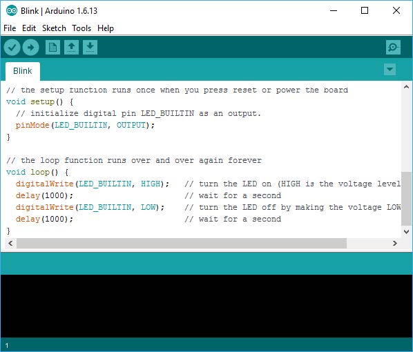
サンプルプログラム

カードチェック

// I2C・SPI用
#include <Wire.h>
#include <SPI.h>

// 画面用
#include <Adafruit_GFX.h>
#include <Adafruit_SSD1306.h>
#define SCREEN_WIDTH 128
#define SCREEN_HEIGHT 64
#define OLED_RESET     4
#define SCREEN_ADDRESS 0x3C
Adafruit_SSD1306 display(SCREEN_WIDTH, SCREEN_HEIGHT, &Wire, OLED_RESET);
#define NUMFLAKES     10
#define LOGO_HEIGHT   16
#define LOGO_WIDTH    16

// NFCリーダー用
#include "Adafruit_PN532.h"
#define PN532_IRQ   (0)
#define PN532_RESET (0)  // Not connected
Adafruit_PN532 nfc(PN532_IRQ, PN532_RESET);

//  ftDuino用
#include <FtduinoSimple.h>

// タグ情報
uint8_t ID1[] = {0x27, 0x86, 0x88, 0x03};
uint8_t ID2[] = {0x0F, 0x3A, 0x88, 0x03};
uint8_t ID3[] = {0xDC, 0x5A, 0x18, 0x4A};
uint8_t ID4[] = {0xFF, 0xF4, 0x6D, 0x03};
uint8_t ID5[] = {0x5D, 0xAA, 0x6D, 0x03};


void setup(void) {

  Serial.begin(9600);
  if (!display.begin(SSD1306_SWITCHCAPVCC, SCREEN_ADDRESS)) {
    Serial.println(F("SSD1306 allocation failed"));
    for (;;); // Don't proceed, loop forever
  }

  display.clearDisplay();  //  バッファを空にする
  display.setTextSize(2); // テキストサイズの設定
  display.setTextColor(SSD1306_WHITE);  //  文字の色
  display.setCursor(10, 0);  //  カーソルの位置
  display.println(F(" Waiting "));  // Flush ram から直接読む
  display.display();      // 画面の更新

  Serial.begin(115200);
  // USBを最大3秒待つ
  uint32_t to = millis();
  while ((!Serial) && ((millis() - to) < 3000))
    delay(10);

  nfc.begin();

  uint32_t versiondata = nfc.getFirmwareVersion();  // ファームウェアのバージョン情報を取得
  // バージョン情報を取得できない場合
  if (! versiondata) {
    Serial.print("== NFCリーダーが見つかりません ==");
    while (1); //  ストップ
  }

  // バージョン情報を表示
  Serial.print("Found chip PN5"); Serial.println((versiondata >> 24) & 0xFF, HEX);
  Serial.print("Firmware ver. "); Serial.print((versiondata >> 16) & 0xFF, DEC);
  Serial.print('.'); Serial.println((versiondata >> 8) & 0xFF, DEC);

  nfc.SAMConfig();

  Serial.println("待機中 ... ");

  // 内部LED  ON
  pinMode(LED_BUILTIN, OUTPUT);
  digitalWrite(LED_BUILTIN, HIGH);
}

void loop(void) {
  static uint8_t registered_uid[4];  //  UID Valueを格納
  static bool registered = false;

  uint8_t uid[] = { 0, 0, 0, 0, 0, 0, 0 };  // 返されたUIDを格納するためのバッファ
  uint8_t uidLength;                        // UIDの長さ(ISO14443Aカードのタイプに応じて4バイトまたは7バイト)

  // ISO14443Aタイプのカード(Mifareなど)を待ちます。
  // 'uid' には UID Valueが入ります 16進数
  // uidLength には UID Lengthが入ります (バイト数)
  if (nfc.readPassiveTargetID(PN532_MIFARE_ISO14443A, uid, &uidLength, 100)) {
    // カードの基本情報を表示
    Serial.println("Found an ISO14443A card");
    Serial.print("  UID Length: "); Serial.print(uidLength, DEC); Serial.println(" bytes");
    Serial.print("  UID Value: ");  nfc.PrintHex(uid, uidLength);
    Serial.println("");
    memcpy(registered_uid, uid, uidLength);

    if (uidLength == 4) {
      Serial.println("Mifare Classic card (4 byte UID)");
      Serial.println("マイフェア クラシックカードです");


      if (memcmp(registered_uid, ID1, uidLength) == 0) {
        Serial.println("カードを受け付けました");
        Serial.println("==  ABE ==");
        // 名前の表示
        display.clearDisplay();  //  バッファを空にする
        display.setCursor(10, 0);  //  カーソルの位置
        display.println("ABE");
        display.display();      // 画面の更新
      }
      if (memcmp(registered_uid, ID2, uidLength) == 0) {
        Serial.println("カードを受け付けました");
        Serial.println("==  KATOU ==");
        // 名前の表示
        display.clearDisplay();  //  バッファを空にする
        display.setCursor(10, 0);  //  カーソルの位置
        display.println("KATOU");
        display.display();      // 画面の更新
      }
      if (memcmp(registered_uid, ID3, uidLength) == 0) {
        Serial.println("カードを受け付けました");
        Serial.println("==  SAITOU ==");
        // 名前の表示
        display.clearDisplay();  //  バッファを空にする
        display.setCursor(10, 0);  //  カーソルの位置
        display.println("SAITOU");
        display.display();      // 画面の更新
      }

      if (memcmp(registered_uid, ID4, uidLength) == 0) {
        Serial.println("カードを受け付けました");
        Serial.println("==  YAMADA ==");
        // 名前の表示
        display.clearDisplay();  //  バッファを空にする
        display.setCursor(10, 0);  //  カーソルの位置
        display.println("YAMADA");
        display.display();      // 画面の更新
      }

      if (memcmp(registered_uid, ID5, uidLength) == 0) {
        Serial.println("カードを受け付けました");
        Serial.println("==  MIYAMOTO ==");
        // 名前の表示
        display.clearDisplay();  //  バッファを空にする
        display.setCursor(10, 0);  //  カーソルの位置
        display.println("MIYAMOTO");
        display.display();      // 画面の更新
      }
    }
  } 

}

================= // Adafruit_PN532.cpp
/**************************************************************************/
/*!
    @file     Adafruit_PN532.cpp
    @author   Adafruit Industries
    @license  BSD (see license.txt)
    
          Driver for NXP's PN532 NFC/13.56MHz RFID Transceiver

          This is a library for the Adafruit PN532 NFC/RFID breakout boards
          This library works with the Adafruit NFC breakout
          ----> https://www.adafruit.com/products/364

          Check out the links above for our tutorials and wiring diagrams
          These chips use SPI or I2C to communicate.

          https://www.nxp.com/docs/en/user-guide/141520.pdf

          Adafruit invests time and resources providing this open source code,
          please support Adafruit and open-source hardware by purchasing
          products from Adafruit!

    @section  HISTORY

    v2.1 - Added NTAG2xx helper functions

    v2.0 - Refactored to add I2C support from Adafruit_NFCShield_I2C library.

    v1.4 - Added setPassiveActivationRetries()

    v1.2 - Added writeGPIO()
         - Added readGPIO()

    v1.1 - Changed readPassiveTargetID() to handle multiple UID sizes
         - Added the following helper functions for text display
             static void PrintHex(const byte * data, const uint32_t numBytes)
             static void PrintHexChar(const byte * pbtData, const uint32_t
   numBytes)
         - Added the following Mifare Classic functions:
             bool mifareclassic_IsFirstBlock (uint32_t uiBlock)
             bool mifareclassic_IsTrailerBlock (uint32_t uiBlock)
             uint8_t mifareclassic_AuthenticateBlock (uint8_t * uid, uint8_t
   uidLen, uint32_t blockNumber, uint8_t keyNumber, uint8_t * keyData) uint8_t
   mifareclassic_ReadDataBlock (uint8_t blockNumber, uint8_t * data) uint8_t
   mifareclassic_WriteDataBlock (uint8_t blockNumber, uint8_t * data)
         - Added the following Mifare Ultalight functions:
             uint8_t mifareultralight_ReadPage (uint8_t page, uint8_t * buffer)
*/
/**************************************************************************/

#include "Arduino.h"

#include <Wire.h>
#ifdef __SAM3X8E__ // arduino due
#define WIRE Wire1
#else
#define WIRE Wire
#endif

#include <SPI.h>

#include "Adafruit_PN532.h"

byte pn532ack[] = {0x00, 0x00, 0xFF, 0x00, 0xFF, 0x00};
byte pn532response_firmwarevers[] = {0x00, 0x00, 0xFF, 0x06, 0xFA, 0xD5};

// Uncomment these lines to enable debug output for PN532(SPI) and/or MIFARE
// related code

// #define PN532DEBUG
// #define MIFAREDEBUG

// If using Native Port on Arduino Zero or Due define as SerialUSB
#define PN532DEBUGPRINT Serial
//#define PN532DEBUGPRINT SerialUSB

#define PN532_PACKBUFFSIZ 64
byte pn532_packetbuffer[PN532_PACKBUFFSIZ];

#ifndef _BV
#define _BV(bit) (1 << (bit))
#endif

/**************************************************************************/
/*!
    @brief  Sends a single byte via I2C

    @param  x    The byte to send
*/
/**************************************************************************/
static inline void i2c_send(uint8_t x) {
#if ARDUINO >= 100
  WIRE.write((uint8_t)x);
#else
  WIRE.send(x);
#endif
}

/**************************************************************************/
/*!
    @brief  Reads a single byte via I2C
*/
/**************************************************************************/
static inline uint8_t i2c_recv(void) {
#if ARDUINO >= 100
  return WIRE.read();
#else
  return WIRE.receive();
#endif
}

/**************************************************************************/
/*!
    @brief  Instantiates a new PN532 class using software SPI.

    @param  clk       SPI clock pin (SCK)
    @param  miso      SPI MISO pin
    @param  mosi      SPI MOSI pin
    @param  ss        SPI chip select pin (CS/SSEL)
*/
/**************************************************************************/
Adafruit_PN532::Adafruit_PN532(uint8_t clk, uint8_t miso, uint8_t mosi,
                               uint8_t ss) {
  spi_dev = new Adafruit_SPIDevice(ss, clk, miso, mosi, 1000000,
                                   SPI_BITORDER_LSBFIRST, SPI_MODE0);
}

/**************************************************************************/
/*!
    @brief  Instantiates a new PN532 class using I2C.

    @param  irq       Location of the IRQ pin
    @param  reset     Location of the RSTPD_N pin
*/
/**************************************************************************/
Adafruit_PN532::Adafruit_PN532(uint8_t irq, uint8_t reset)
    : _irq(irq), _reset(reset) {
  pinMode(_irq, INPUT);
  pinMode(_reset, OUTPUT);
}

/**************************************************************************/
/*!
    @brief  Instantiates a new PN532 class using hardware SPI.

    @param  ss        SPI chip select pin (CS/SSEL)
*/
/**************************************************************************/
Adafruit_PN532::Adafruit_PN532(uint8_t ss) {
  spi_dev =
      new Adafruit_SPIDevice(ss, 1000000, SPI_BITORDER_LSBFIRST, SPI_MODE0);
}

/**************************************************************************/
/*!
    @brief  Setups the HW
*/
/**************************************************************************/
void Adafruit_PN532::begin() {
  if (spi_dev != NULL) {
    // SPI initialization
    spi_dev->begin();

    // not exactly sure why but we have to send a dummy command to get synced up
    pn532_packetbuffer[0] = PN532_COMMAND_GETFIRMWAREVERSION;
    sendCommandCheckAck(pn532_packetbuffer, 1);
    // ignore response!
  } else {
    // I2C initialization.
    WIRE.begin();
    if(_reset) {
      // Reset the PN532
      digitalWrite(_reset, HIGH);
      digitalWrite(_reset, LOW);
      delay(400);
      digitalWrite(_reset, HIGH);
      delay(
        10); // Small delay required before taking other actions after reset.
             // See timing diagram on page 209 of the datasheet, section 12.23.
    }
  }
}

/**************************************************************************/
/*!
    @brief  Prints a hexadecimal value in plain characters

    @param  data      Pointer to the byte data
    @param  numBytes  Data length in bytes
*/
/**************************************************************************/
void Adafruit_PN532::PrintHex(const byte *data, const uint32_t numBytes) {
  uint32_t szPos;
  for (szPos = 0; szPos < numBytes; szPos++) {
    PN532DEBUGPRINT.print(F("0x"));
    // Append leading 0 for small values
    if (data[szPos] <= 0xF)
      PN532DEBUGPRINT.print(F("0"));
    PN532DEBUGPRINT.print(data[szPos] & 0xff, HEX);
    if ((numBytes > 1) && (szPos != numBytes - 1)) {
      PN532DEBUGPRINT.print(F(" "));
    }
  }
  PN532DEBUGPRINT.println();
}

/**************************************************************************/
/*!
    @brief  Prints a hexadecimal value in plain characters, along with
            the char equivalents in the following format

            00 00 00 00 00 00  ......

    @param  data      Pointer to the byte data
    @param  numBytes  Data length in bytes
*/
/**************************************************************************/
void Adafruit_PN532::PrintHexChar(const byte *data, const uint32_t numBytes) {
  uint32_t szPos;
  for (szPos = 0; szPos < numBytes; szPos++) {
    // Append leading 0 for small values
    if (data[szPos] <= 0xF)
      PN532DEBUGPRINT.print(F("0"));
    PN532DEBUGPRINT.print(data[szPos], HEX);
    if ((numBytes > 1) && (szPos != numBytes - 1)) {
      PN532DEBUGPRINT.print(F(" "));
    }
  }
  PN532DEBUGPRINT.print(F("  "));
  for (szPos = 0; szPos < numBytes; szPos++) {
    if (data[szPos] <= 0x1F)
      PN532DEBUGPRINT.print(F("."));
    else
      PN532DEBUGPRINT.print((char)data[szPos]);
  }
  PN532DEBUGPRINT.println();
}

/**************************************************************************/
/*!
    @brief  Checks the firmware version of the PN5xx chip

    @returns  The chip's firmware version and ID
*/
/**************************************************************************/
uint32_t Adafruit_PN532::getFirmwareVersion(void) {
  uint32_t response;

  pn532_packetbuffer[0] = PN532_COMMAND_GETFIRMWAREVERSION;

  if (!sendCommandCheckAck(pn532_packetbuffer, 1)) {
    return 0;
  }

  // read data packet
  readdata(pn532_packetbuffer, 12);

  // check some basic stuff
  if (0 != memcmp((char *)pn532_packetbuffer,
                  (char *)pn532response_firmwarevers, 6)) {
#ifdef PN532DEBUG
    PN532DEBUGPRINT.println(F("Firmware doesn't match!"));
#endif
    return 0;
  }

  int offset = 7;
  response = pn532_packetbuffer[offset++];
  response <<= 8;
  response |= pn532_packetbuffer[offset++];
  response <<= 8;
  response |= pn532_packetbuffer[offset++];
  response <<= 8;
  response |= pn532_packetbuffer[offset++];

  return response;
}

/**************************************************************************/
/*!
    @brief  Sends a command and waits a specified period for the ACK

    @param  cmd       Pointer to the command buffer
    @param  cmdlen    The size of the command in bytes
    @param  timeout   timeout before giving up

    @returns  1 if everything is OK, 0 if timeout occured before an
              ACK was recieved
*/
/**************************************************************************/
// default timeout of one second
bool Adafruit_PN532::sendCommandCheckAck(uint8_t *cmd, uint8_t cmdlen,
                                         uint16_t timeout) {
  // uint16_t timer = 0;

  // write the command
  writecommand(cmd, cmdlen);

  // Wait for chip to say its ready!
  if (!waitready(timeout)) {
    return false;
  }
  
#ifdef PN532DEBUG
  if (spi_dev == NULL) {
    PN532DEBUGPRINT.println(F("IRQ received"));
  }
#endif

  // read acknowledgement
  if (!readack()) {
#ifdef PN532DEBUG
    PN532DEBUGPRINT.println(F("No ACK frame received!"));
#endif
    return false;
  }

  // For SPI only wait for the chip to be ready again.
  // This is unnecessary with I2C.
  if (spi_dev != NULL) {
    if (!waitready(timeout)) {
      return false;
    }
  }

  return true; // ack'd command
}

/**************************************************************************/
/*!
    Writes an 8-bit value that sets the state of the PN532's GPIO pins

    @warning This function is provided exclusively for board testing and
             is dangerous since it will throw an error if any pin other
             than the ones marked "Can be used as GPIO" are modified!  All
             pins that can not be used as GPIO should ALWAYS be left high
             (value = 1) or the system will become unstable and a HW reset
             will be required to recover the PN532.

             pinState[0]  = P30     Can be used as GPIO
             pinState[1]  = P31     Can be used as GPIO
             pinState[2]  = P32     *** RESERVED (Must be 1!) ***
             pinState[3]  = P33     Can be used as GPIO
             pinState[4]  = P34     *** RESERVED (Must be 1!) ***
             pinState[5]  = P35     Can be used as GPIO

    @returns 1 if everything executed properly, 0 for an error
*/
/**************************************************************************/
bool Adafruit_PN532::writeGPIO(uint8_t pinstate) {
  // uint8_t errorbit;

  // Make sure pinstate does not try to toggle P32 or P34
  pinstate |= (1 << PN532_GPIO_P32) | (1 << PN532_GPIO_P34);

  // Fill command buffer
  pn532_packetbuffer[0] = PN532_COMMAND_WRITEGPIO;
  pn532_packetbuffer[1] = PN532_GPIO_VALIDATIONBIT | pinstate; // P3 Pins
  pn532_packetbuffer[2] = 0x00; // P7 GPIO Pins (not used ... taken by SPI)

#ifdef PN532DEBUG
  PN532DEBUGPRINT.print(F("Writing P3 GPIO: "));
  PN532DEBUGPRINT.println(pn532_packetbuffer[1], HEX);
#endif

  // Send the WRITEGPIO command (0x0E)
  if (!sendCommandCheckAck(pn532_packetbuffer, 3))
    return 0x0;

  // Read response packet (00 FF PLEN PLENCHECKSUM D5 CMD+1(0x0F) DATACHECKSUM
  // 00)
  readdata(pn532_packetbuffer, 8);

#ifdef PN532DEBUG
  PN532DEBUGPRINT.print(F("Received: "));
  PrintHex(pn532_packetbuffer, 8);
  PN532DEBUGPRINT.println();
#endif

  int offset = 6;
  return (pn532_packetbuffer[offset] == 0x0F);
}

/**************************************************************************/
/*!
    Reads the state of the PN532's GPIO pins

    @returns An 8-bit value containing the pin state where:

             pinState[0]  = P30
             pinState[1]  = P31
             pinState[2]  = P32
             pinState[3]  = P33
             pinState[4]  = P34
             pinState[5]  = P35
*/
/**************************************************************************/
uint8_t Adafruit_PN532::readGPIO(void) {
  pn532_packetbuffer[0] = PN532_COMMAND_READGPIO;

  // Send the READGPIO command (0x0C)
  if (!sendCommandCheckAck(pn532_packetbuffer, 1))
    return 0x0;

  // Read response packet (00 FF PLEN PLENCHECKSUM D5 CMD+1(0x0D) P3 P7 IO1
  // DATACHECKSUM 00)
  readdata(pn532_packetbuffer, 11);

  /* READGPIO response should be in the following format:

    byte            Description
    -------------   ------------------------------------------
    b0..5           Frame header and preamble (with I2C there is an extra 0x00)
    b6              P3 GPIO Pins
    b7              P7 GPIO Pins (not used ... taken by SPI)
    b8              Interface Mode Pins (not used ... bus select pins)
    b9..10          checksum */

  int p3offset = 7;

#ifdef PN532DEBUG
  PN532DEBUGPRINT.print(F("Received: "));
  PrintHex(pn532_packetbuffer, 11);
  PN532DEBUGPRINT.println();
  PN532DEBUGPRINT.print(F("P3 GPIO: 0x"));
  PN532DEBUGPRINT.println(pn532_packetbuffer[p3offset], HEX);
  PN532DEBUGPRINT.print(F("P7 GPIO: 0x"));
  PN532DEBUGPRINT.println(pn532_packetbuffer[p3offset + 1], HEX);
  PN532DEBUGPRINT.print(F("IO GPIO: 0x"));
  PN532DEBUGPRINT.println(pn532_packetbuffer[p3offset + 2], HEX);
  // Note: You can use the IO GPIO value to detect the serial bus being used
  switch (pn532_packetbuffer[p3offset + 2]) {
  case 0x00: // Using UART
    PN532DEBUGPRINT.println(F("Using UART (IO = 0x00)"));
    break;
  case 0x01: // Using I2C
    PN532DEBUGPRINT.println(F("Using I2C (IO = 0x01)"));
    break;
  case 0x02: // Using SPI
    PN532DEBUGPRINT.println(F("Using SPI (IO = 0x02)"));
    break;
  }
#endif

  return pn532_packetbuffer[p3offset];
}

/**************************************************************************/
/*!
    @brief  Configures the SAM (Secure Access Module)
*/
/**************************************************************************/
bool Adafruit_PN532::SAMConfig(void) {
  pn532_packetbuffer[0] = PN532_COMMAND_SAMCONFIGURATION;
  pn532_packetbuffer[1] = 0x01; // normal mode;
  pn532_packetbuffer[2] = 0x14; // timeout 50ms * 20 = 1 second
  pn532_packetbuffer[3] = 0x01; // use IRQ pin!

  if (!sendCommandCheckAck(pn532_packetbuffer, 4))
    return false;

  // read data packet
  readdata(pn532_packetbuffer, 8);

  int offset = 6;
  return (pn532_packetbuffer[offset] == 0x15);
}

/**************************************************************************/
/*!
    Sets the MxRtyPassiveActivation byte of the RFConfiguration register

    @param  maxRetries    0xFF to wait forever, 0x00..0xFE to timeout
                          after mxRetries

    @returns 1 if everything executed properly, 0 for an error
*/
/**************************************************************************/
bool Adafruit_PN532::setPassiveActivationRetries(uint8_t maxRetries) {
  pn532_packetbuffer[0] = PN532_COMMAND_RFCONFIGURATION;
  pn532_packetbuffer[1] = 5;    // Config item 5 (MaxRetries)
  pn532_packetbuffer[2] = 0xFF; // MxRtyATR (default = 0xFF)
  pn532_packetbuffer[3] = 0x01; // MxRtyPSL (default = 0x01)
  pn532_packetbuffer[4] = maxRetries;

#ifdef MIFAREDEBUG
  PN532DEBUGPRINT.print(F("Setting MxRtyPassiveActivation to "));
  PN532DEBUGPRINT.print(maxRetries, DEC);
  PN532DEBUGPRINT.println(F(" "));
#endif

  if (!sendCommandCheckAck(pn532_packetbuffer, 5))
    return 0x0; // no ACK

  return 1;
}

/***** ISO14443A Commands ******/

/**************************************************************************/
/*!
    Waits for an ISO14443A target to enter the field

    @param  cardBaudRate  Baud rate of the card
    @param  uid           Pointer to the array that will be populated
                          with the card's UID (up to 7 bytes)
    @param  uidLength     Pointer to the variable that will hold the
                          length of the card's UID.

    @returns 1 if everything executed properly, 0 for an error
*/
/**************************************************************************/
bool Adafruit_PN532::readPassiveTargetID(uint8_t cardbaudrate, uint8_t *uid,
                                         uint8_t *uidLength, uint16_t timeout) {
  pn532_packetbuffer[0] = PN532_COMMAND_INLISTPASSIVETARGET;
  pn532_packetbuffer[1] = 1; // max 1 cards at once (we can set this to 2 later)
  pn532_packetbuffer[2] = cardbaudrate;

  // TH: this will always ack (at least for i2c) and will _not_ timeout if no cards are present
  if (!sendCommandCheckAck(pn532_packetbuffer, 3, timeout)) {
#ifdef PN532DEBUG
    PN532DEBUGPRINT.println(F("No card(s) read"));
#endif
    return 0x0; // no cards read
  }

  // wait for a card to enter the field (only possible with I2C)
  if (spi_dev == NULL) {
#ifdef PN532DEBUG
    PN532DEBUGPRINT.println(F("Waiting for IRQ (indicates card presence)"));
#endif
    if (!waitready(timeout)) {
#ifdef PN532DEBUG
      PN532DEBUGPRINT.println(F("IRQ Timeout"));
#endif
      return 0x0;
    }    
  }

  // read data packet
  readdata(pn532_packetbuffer, 20);
  // check some basic stuff

  /* ISO14443A card response should be in the following format:

    byte            Description
    -------------   ------------------------------------------
    b0..6           Frame header and preamble
    b7              Tags Found
    b8              Tag Number (only one used in this example)
    b9..10          SENS_RES
    b11             SEL_RES
    b12             NFCID Length
    b13..NFCIDLen   NFCID                                      */

#ifdef MIFAREDEBUG
  PN532DEBUGPRINT.print(F("Found "));
  PN532DEBUGPRINT.print(pn532_packetbuffer[7], DEC);
  PN532DEBUGPRINT.println(F(" tags"));
#endif
  if (pn532_packetbuffer[7] != 1)
    return 0;

  uint16_t sens_res = pn532_packetbuffer[9];
  sens_res <<= 8;
  sens_res |= pn532_packetbuffer[10];
#ifdef MIFAREDEBUG
  PN532DEBUGPRINT.print(F("ATQA: 0x"));
  PN532DEBUGPRINT.println(sens_res, HEX);
  PN532DEBUGPRINT.print(F("SAK: 0x"));
  PN532DEBUGPRINT.println(pn532_packetbuffer[11], HEX);
#endif

  /* Card appears to be Mifare Classic */
  *uidLength = pn532_packetbuffer[12];
#ifdef MIFAREDEBUG
  PN532DEBUGPRINT.print(F("UID:"));
#endif
  for (uint8_t i = 0; i < pn532_packetbuffer[12]; i++) {
    uid[i] = pn532_packetbuffer[13 + i];
#ifdef MIFAREDEBUG
    PN532DEBUGPRINT.print(F(" 0x"));
    PN532DEBUGPRINT.print(uid[i], HEX);
#endif
  }
#ifdef MIFAREDEBUG
  PN532DEBUGPRINT.println();
#endif

  return 1;
}

/**************************************************************************/
/*!
    @brief  Exchanges an APDU with the currently inlisted peer

    @param  send            Pointer to data to send
    @param  sendLength      Length of the data to send
    @param  response        Pointer to response data
    @param  responseLength  Pointer to the response data length
*/
/**************************************************************************/
bool Adafruit_PN532::inDataExchange(uint8_t *send, uint8_t sendLength,
                                    uint8_t *response,
                                    uint8_t *responseLength) {
  if (sendLength > PN532_PACKBUFFSIZ - 2) {
#ifdef PN532DEBUG
    PN532DEBUGPRINT.println(F("APDU length too long for packet buffer"));
#endif
    return false;
  }
  uint8_t i;

  pn532_packetbuffer[0] = 0x40; // PN532_COMMAND_INDATAEXCHANGE;
  pn532_packetbuffer[1] = _inListedTag;
  for (i = 0; i < sendLength; ++i) {
    pn532_packetbuffer[i + 2] = send[i];
  }

  if (!sendCommandCheckAck(pn532_packetbuffer, sendLength + 2, 1000)) {
#ifdef PN532DEBUG
    PN532DEBUGPRINT.println(F("Could not send APDU"));
#endif
    return false;
  }

  if (!waitready(1000)) {
#ifdef PN532DEBUG
    PN532DEBUGPRINT.println(F("Response never received for APDU..."));
#endif
    return false;
  }

  readdata(pn532_packetbuffer, sizeof(pn532_packetbuffer));

  if (pn532_packetbuffer[0] == 0 && pn532_packetbuffer[1] == 0 &&
      pn532_packetbuffer[2] == 0xff) {
    uint8_t length = pn532_packetbuffer[3];
    if (pn532_packetbuffer[4] != (uint8_t)(~length + 1)) {
#ifdef PN532DEBUG
      PN532DEBUGPRINT.println(F("Length check invalid"));
      PN532DEBUGPRINT.println(length, HEX);
      PN532DEBUGPRINT.println((~length) + 1, HEX);
#endif
      return false;
    }
    if (pn532_packetbuffer[5] == PN532_PN532TOHOST &&
        pn532_packetbuffer[6] == PN532_RESPONSE_INDATAEXCHANGE) {
      if ((pn532_packetbuffer[7] & 0x3f) != 0) {
#ifdef PN532DEBUG
        PN532DEBUGPRINT.println(F("Status code indicates an error"));
#endif
        return false;
      }

      length -= 3;

      if (length > *responseLength) {
        length = *responseLength; // silent truncation...
      }

      for (i = 0; i < length; ++i) {
        response[i] = pn532_packetbuffer[8 + i];
      }
      *responseLength = length;

      return true;
    } else {
      PN532DEBUGPRINT.print(F("Don't know how to handle this command: "));
      PN532DEBUGPRINT.println(pn532_packetbuffer[6], HEX);
      return false;
    }
  } else {
    PN532DEBUGPRINT.println(F("Preamble missing"));
    return false;
  }
}

/**************************************************************************/
/*!
    @brief  'InLists' a passive target. PN532 acting as reader/initiator,
            peer acting as card/responder.
*/
/**************************************************************************/
bool Adafruit_PN532::inListPassiveTarget() {
  pn532_packetbuffer[0] = PN532_COMMAND_INLISTPASSIVETARGET;
  pn532_packetbuffer[1] = 1;
  pn532_packetbuffer[2] = 0;

#ifdef PN532DEBUG
  PN532DEBUGPRINT.print(F("About to inList passive target"));
#endif

  if (!sendCommandCheckAck(pn532_packetbuffer, 3, 1000)) {
#ifdef PN532DEBUG
    PN532DEBUGPRINT.println(F("Could not send inlist message"));
#endif
    return false;
  }

  if (!waitready(30000)) {
    return false;
  }

  readdata(pn532_packetbuffer, sizeof(pn532_packetbuffer));

  if (pn532_packetbuffer[0] == 0 && pn532_packetbuffer[1] == 0 &&
      pn532_packetbuffer[2] == 0xff) {
    uint8_t length = pn532_packetbuffer[3];
    if (pn532_packetbuffer[4] != (uint8_t)(~length + 1)) {
#ifdef PN532DEBUG
      PN532DEBUGPRINT.println(F("Length check invalid"));
      PN532DEBUGPRINT.println(length, HEX);
      PN532DEBUGPRINT.println((~length) + 1, HEX);
#endif
      return false;
    }
    if (pn532_packetbuffer[5] == PN532_PN532TOHOST &&
        pn532_packetbuffer[6] == PN532_RESPONSE_INLISTPASSIVETARGET) {
      if (pn532_packetbuffer[7] != 1) {
#ifdef PN532DEBUG
        PN532DEBUGPRINT.println(F("Unhandled number of targets inlisted"));
#endif
        PN532DEBUGPRINT.println(F("Number of tags inlisted:"));
        PN532DEBUGPRINT.println(pn532_packetbuffer[7]);
        return false;
      }

      _inListedTag = pn532_packetbuffer[8];
      PN532DEBUGPRINT.print(F("Tag number: "));
      PN532DEBUGPRINT.println(_inListedTag);

      return true;
    } else {
#ifdef PN532DEBUG
      PN532DEBUGPRINT.print(F("Unexpected response to inlist passive host"));
#endif
      return false;
    }
  } else {
#ifdef PN532DEBUG
    PN532DEBUGPRINT.println(F("Preamble missing"));
#endif
    return false;
  }

  return true;
}

/***** Mifare Classic Functions ******/

/**************************************************************************/
/*!
      Indicates whether the specified block number is the first block
      in the sector (block 0 relative to the current sector)
*/
/**************************************************************************/
bool Adafruit_PN532::mifareclassic_IsFirstBlock(uint32_t uiBlock) {
  // Test if we are in the small or big sectors
  if (uiBlock < 128)
    return ((uiBlock) % 4 == 0);
  else
    return ((uiBlock) % 16 == 0);
}

/**************************************************************************/
/*!
      Indicates whether the specified block number is the sector trailer
*/
/**************************************************************************/
bool Adafruit_PN532::mifareclassic_IsTrailerBlock(uint32_t uiBlock) {
  // Test if we are in the small or big sectors
  if (uiBlock < 128)
    return ((uiBlock + 1) % 4 == 0);
  else
    return ((uiBlock + 1) % 16 == 0);
}

/**************************************************************************/
/*!
    Tries to authenticate a block of memory on a MIFARE card using the
    INDATAEXCHANGE command.  See section 7.3.8 of the PN532 User Manual
    for more information on sending MIFARE and other commands.

    @param  uid           Pointer to a byte array containing the card UID
    @param  uidLen        The length (in bytes) of the card's UID (Should
                          be 4 for MIFARE Classic)
    @param  blockNumber   The block number to authenticate.  (0..63 for
                          1KB cards, and 0..255 for 4KB cards).
    @param  keyNumber     Which key type to use during authentication
                          (0 = MIFARE_CMD_AUTH_A, 1 = MIFARE_CMD_AUTH_B)
    @param  keyData       Pointer to a byte array containing the 6 byte
                          key value

    @returns 1 if everything executed properly, 0 for an error
*/
/**************************************************************************/
uint8_t Adafruit_PN532::mifareclassic_AuthenticateBlock(uint8_t *uid,
                                                        uint8_t uidLen,
                                                        uint32_t blockNumber,
                                                        uint8_t keyNumber,
                                                        uint8_t *keyData) {
  // uint8_t len;
  uint8_t i;

  // Hang on to the key and uid data
  memcpy(_key, keyData, 6);
  memcpy(_uid, uid, uidLen);
  _uidLen = uidLen;

#ifdef MIFAREDEBUG
  PN532DEBUGPRINT.print(F("Trying to authenticate card "));
  Adafruit_PN532::PrintHex(_uid, _uidLen);
  PN532DEBUGPRINT.print(F("Using authentication KEY "));
  PN532DEBUGPRINT.print(keyNumber ? 'B' : 'A');
  PN532DEBUGPRINT.print(F(": "));
  Adafruit_PN532::PrintHex(_key, 6);
#endif

  // Prepare the authentication command //
  pn532_packetbuffer[0] =
      PN532_COMMAND_INDATAEXCHANGE; /* Data Exchange Header */
  pn532_packetbuffer[1] = 1;        /* Max card numbers */
  pn532_packetbuffer[2] = (keyNumber) ? MIFARE_CMD_AUTH_B : MIFARE_CMD_AUTH_A;
  pn532_packetbuffer[3] =
      blockNumber; /* Block Number (1K = 0..63, 4K = 0..255 */
  memcpy(pn532_packetbuffer + 4, _key, 6);
  for (i = 0; i < _uidLen; i++) {
    pn532_packetbuffer[10 + i] = _uid[i]; /* 4 byte card ID */
  }

  if (!sendCommandCheckAck(pn532_packetbuffer, 10 + _uidLen))
    return 0;

  // Read the response packet
  readdata(pn532_packetbuffer, 12);

  // check if the response is valid and we are authenticated???
  // for an auth success it should be bytes 5-7: 0xD5 0x41 0x00
  // Mifare auth error is technically byte 7: 0x14 but anything other and 0x00
  // is not good
  if (pn532_packetbuffer[7] != 0x00) {
#ifdef PN532DEBUG
    PN532DEBUGPRINT.print(F("Authentification failed: "));
    Adafruit_PN532::PrintHexChar(pn532_packetbuffer, 12);
#endif
    return 0;
  }

  return 1;
}

/**************************************************************************/
/*!
    Tries to read an entire 16-byte data block at the specified block
    address.

    @param  blockNumber   The block number to authenticate.  (0..63 for
                          1KB cards, and 0..255 for 4KB cards).
    @param  data          Pointer to the byte array that will hold the
                          retrieved data (if any)

    @returns 1 if everything executed properly, 0 for an error
*/
/**************************************************************************/
uint8_t Adafruit_PN532::mifareclassic_ReadDataBlock(uint8_t blockNumber,
                                                    uint8_t *data) {
#ifdef MIFAREDEBUG
  PN532DEBUGPRINT.print(F("Trying to read 16 bytes from block "));
  PN532DEBUGPRINT.println(blockNumber);
#endif

  /* Prepare the command */
  pn532_packetbuffer[0] = PN532_COMMAND_INDATAEXCHANGE;
  pn532_packetbuffer[1] = 1;               /* Card number */
  pn532_packetbuffer[2] = MIFARE_CMD_READ; /* Mifare Read command = 0x30 */
  pn532_packetbuffer[3] =
      blockNumber; /* Block Number (0..63 for 1K, 0..255 for 4K) */

  /* Send the command */
  if (!sendCommandCheckAck(pn532_packetbuffer, 4)) {
#ifdef MIFAREDEBUG
    PN532DEBUGPRINT.println(F("Failed to receive ACK for read command"));
#endif
    return 0;
  }

  /* Read the response packet */
  readdata(pn532_packetbuffer, 26);

  /* If byte 8 isn't 0x00 we probably have an error */
  if (pn532_packetbuffer[7] != 0x00) {
#ifdef MIFAREDEBUG
    PN532DEBUGPRINT.println(F("Unexpected response"));
    Adafruit_PN532::PrintHexChar(pn532_packetbuffer, 26);
#endif
    return 0;
  }

  /* Copy the 16 data bytes to the output buffer        */
  /* Block content starts at byte 9 of a valid response */
  memcpy(data, pn532_packetbuffer + 8, 16);

/* Display data for debug if requested */
#ifdef MIFAREDEBUG
  PN532DEBUGPRINT.print(F("Block "));
  PN532DEBUGPRINT.println(blockNumber);
  Adafruit_PN532::PrintHexChar(data, 16);
#endif

  return 1;
}

/**************************************************************************/
/*!
    Tries to write an entire 16-byte data block at the specified block
    address.

    @param  blockNumber   The block number to authenticate.  (0..63 for
                          1KB cards, and 0..255 for 4KB cards).
    @param  data          The byte array that contains the data to write.

    @returns 1 if everything executed properly, 0 for an error
*/
/**************************************************************************/
uint8_t Adafruit_PN532::mifareclassic_WriteDataBlock(uint8_t blockNumber,
                                                     uint8_t *data) {
#ifdef MIFAREDEBUG
  PN532DEBUGPRINT.print(F("Trying to write 16 bytes to block "));
  PN532DEBUGPRINT.println(blockNumber);
#endif

  /* Prepare the first command */
  pn532_packetbuffer[0] = PN532_COMMAND_INDATAEXCHANGE;
  pn532_packetbuffer[1] = 1;                /* Card number */
  pn532_packetbuffer[2] = MIFARE_CMD_WRITE; /* Mifare Write command = 0xA0 */
  pn532_packetbuffer[3] =
      blockNumber; /* Block Number (0..63 for 1K, 0..255 for 4K) */
  memcpy(pn532_packetbuffer + 4, data, 16); /* Data Payload */

  /* Send the command */
  if (!sendCommandCheckAck(pn532_packetbuffer, 20)) {
#ifdef MIFAREDEBUG
    PN532DEBUGPRINT.println(F("Failed to receive ACK for write command"));
#endif
    return 0;
  }
  delay(10);

  /* Read the response packet */
  readdata(pn532_packetbuffer, 26);

  return 1;
}

/**************************************************************************/
/*!
    Formats a Mifare Classic card to store NDEF Records

    @returns 1 if everything executed properly, 0 for an error
*/
/**************************************************************************/
uint8_t Adafruit_PN532::mifareclassic_FormatNDEF(void) {
  uint8_t sectorbuffer1[16] = {0x14, 0x01, 0x03, 0xE1, 0x03, 0xE1, 0x03, 0xE1,
                               0x03, 0xE1, 0x03, 0xE1, 0x03, 0xE1, 0x03, 0xE1};
  uint8_t sectorbuffer2[16] = {0x03, 0xE1, 0x03, 0xE1, 0x03, 0xE1, 0x03, 0xE1,
                               0x03, 0xE1, 0x03, 0xE1, 0x03, 0xE1, 0x03, 0xE1};
  uint8_t sectorbuffer3[16] = {0xA0, 0xA1, 0xA2, 0xA3, 0xA4, 0xA5, 0x78, 0x77,
                               0x88, 0xC1, 0xFF, 0xFF, 0xFF, 0xFF, 0xFF, 0xFF};

  // Note 0xA0 0xA1 0xA2 0xA3 0xA4 0xA5 must be used for key A
  // for the MAD sector in NDEF records (sector 0)

  // Write block 1 and 2 to the card
  if (!(mifareclassic_WriteDataBlock(1, sectorbuffer1)))
    return 0;
  if (!(mifareclassic_WriteDataBlock(2, sectorbuffer2)))
    return 0;
  // Write key A and access rights card
  if (!(mifareclassic_WriteDataBlock(3, sectorbuffer3)))
    return 0;

  // Seems that everything was OK (?!)
  return 1;
}

/**************************************************************************/
/*!
    Writes an NDEF URI Record to the specified sector (1..15)

    Note that this function assumes that the Mifare Classic card is
    already formatted to work as an "NFC Forum Tag" and uses a MAD1
    file system.  You can use the NXP TagWriter app on Android to
    properly format cards for this.

    @param  sectorNumber  The sector that the URI record should be written
                          to (can be 1..15 for a 1K card)
    @param  uriIdentifier The uri identifier code (0 = none, 0x01 =
                          "http://www.", etc.)
    @param  url           The uri text to write (max 38 characters).

    @returns 1 if everything executed properly, 0 for an error
*/
/**************************************************************************/
uint8_t Adafruit_PN532::mifareclassic_WriteNDEFURI(uint8_t sectorNumber,
                                                   uint8_t uriIdentifier,
                                                   const char *url) {
  // Figure out how long the string is
  uint8_t len = strlen(url);

  // Make sure we're within a 1K limit for the sector number
  if ((sectorNumber < 1) || (sectorNumber > 15))
    return 0;

  // Make sure the URI payload is between 1 and 38 chars
  if ((len < 1) || (len > 38))
    return 0;

  // Note 0xD3 0xF7 0xD3 0xF7 0xD3 0xF7 must be used for key A
  // in NDEF records

  // Setup the sector buffer (w/pre-formatted TLV wrapper and NDEF message)
  uint8_t sectorbuffer1[16] = {0x00,
                               0x00,
                               0x03,
                               (uint8_t)(len + 5),
                               0xD1,
                               0x01,
                               (uint8_t)(len + 1),
                               0x55,
                               uriIdentifier,
                               0x00,
                               0x00,
                               0x00,
                               0x00,
                               0x00,
                               0x00,
                               0x00};
  uint8_t sectorbuffer2[16] = {0x00, 0x00, 0x00, 0x00, 0x00, 0x00, 0x00, 0x00,
                               0x00, 0x00, 0x00, 0x00, 0x00, 0x00, 0x00, 0x00};
  uint8_t sectorbuffer3[16] = {0x00, 0x00, 0x00, 0x00, 0x00, 0x00, 0x00, 0x00,
                               0x00, 0x00, 0x00, 0x00, 0x00, 0x00, 0x00, 0x00};
  uint8_t sectorbuffer4[16] = {0xD3, 0xF7, 0xD3, 0xF7, 0xD3, 0xF7, 0x7F, 0x07,
                               0x88, 0x40, 0xFF, 0xFF, 0xFF, 0xFF, 0xFF, 0xFF};
  if (len <= 6) {
    // Unlikely we'll get a url this short, but why not ...
    memcpy(sectorbuffer1 + 9, url, len);
    sectorbuffer1[len + 9] = 0xFE;
  } else if (len == 7) {
    // 0xFE needs to be wrapped around to next block
    memcpy(sectorbuffer1 + 9, url, len);
    sectorbuffer2[0] = 0xFE;
  } else if ((len > 7) && (len <= 22)) {
    // Url fits in two blocks
    memcpy(sectorbuffer1 + 9, url, 7);
    memcpy(sectorbuffer2, url + 7, len - 7);
    sectorbuffer2[len - 7] = 0xFE;
  } else if (len == 23) {
    // 0xFE needs to be wrapped around to final block
    memcpy(sectorbuffer1 + 9, url, 7);
    memcpy(sectorbuffer2, url + 7, len - 7);
    sectorbuffer3[0] = 0xFE;
  } else {
    // Url fits in three blocks
    memcpy(sectorbuffer1 + 9, url, 7);
    memcpy(sectorbuffer2, url + 7, 16);
    memcpy(sectorbuffer3, url + 23, len - 24);
    sectorbuffer3[len - 22] = 0xFE;
  }

  // Now write all three blocks back to the card
  if (!(mifareclassic_WriteDataBlock(sectorNumber * 4, sectorbuffer1)))
    return 0;
  if (!(mifareclassic_WriteDataBlock((sectorNumber * 4) + 1, sectorbuffer2)))
    return 0;
  if (!(mifareclassic_WriteDataBlock((sectorNumber * 4) + 2, sectorbuffer3)))
    return 0;
  if (!(mifareclassic_WriteDataBlock((sectorNumber * 4) + 3, sectorbuffer4)))
    return 0;

  // Seems that everything was OK (?!)
  return 1;
}

/***** Mifare Ultralight Functions ******/

/**************************************************************************/
/*!
    Tries to read an entire 4-byte page at the specified address.

    @param  page        The page number (0..63 in most cases)
    @param  buffer      Pointer to the byte array that will hold the
                        retrieved data (if any)
*/
/**************************************************************************/
uint8_t Adafruit_PN532::mifareultralight_ReadPage(uint8_t page,
                                                  uint8_t *buffer) {
  if (page >= 64) {
#ifdef MIFAREDEBUG
    PN532DEBUGPRINT.println(F("Page value out of range"));
#endif
    return 0;
  }

#ifdef MIFAREDEBUG
  PN532DEBUGPRINT.print(F("Reading page "));
  PN532DEBUGPRINT.println(page);
#endif

  /* Prepare the command */
  pn532_packetbuffer[0] = PN532_COMMAND_INDATAEXCHANGE;
  pn532_packetbuffer[1] = 1;               /* Card number */
  pn532_packetbuffer[2] = MIFARE_CMD_READ; /* Mifare Read command = 0x30 */
  pn532_packetbuffer[3] = page; /* Page Number (0..63 in most cases) */

  /* Send the command */
  if (!sendCommandCheckAck(pn532_packetbuffer, 4)) {
#ifdef MIFAREDEBUG
    PN532DEBUGPRINT.println(F("Failed to receive ACK for write command"));
#endif
    return 0;
  }

  /* Read the response packet */
  readdata(pn532_packetbuffer, 26);
#ifdef MIFAREDEBUG
  PN532DEBUGPRINT.println(F("Received: "));
  Adafruit_PN532::PrintHexChar(pn532_packetbuffer, 26);
#endif

  /* If byte 8 isn't 0x00 we probably have an error */
  if (pn532_packetbuffer[7] == 0x00) {
    /* Copy the 4 data bytes to the output buffer         */
    /* Block content starts at byte 9 of a valid response */
    /* Note that the command actually reads 16 byte or 4  */
    /* pages at a time ... we simply discard the last 12  */
    /* bytes                                              */
    memcpy(buffer, pn532_packetbuffer + 8, 4);
  } else {
#ifdef MIFAREDEBUG
    PN532DEBUGPRINT.println(F("Unexpected response reading block: "));
    Adafruit_PN532::PrintHexChar(pn532_packetbuffer, 26);
#endif
    return 0;
  }

/* Display data for debug if requested */
#ifdef MIFAREDEBUG
  PN532DEBUGPRINT.print(F("Page "));
  PN532DEBUGPRINT.print(page);
  PN532DEBUGPRINT.println(F(":"));
  Adafruit_PN532::PrintHexChar(buffer, 4);
#endif

  // Return OK signal
  return 1;
}

/**************************************************************************/
/*!
    Tries to write an entire 4-byte page at the specified block
    address.

    @param  page          The page number to write.  (0..63 for most cases)
    @param  data          The byte array that contains the data to write.
                          Should be exactly 4 bytes long.

    @returns 1 if everything executed properly, 0 for an error
*/
/**************************************************************************/
uint8_t Adafruit_PN532::mifareultralight_WritePage(uint8_t page,
                                                   uint8_t *data) {

  if (page >= 64) {
#ifdef MIFAREDEBUG
    PN532DEBUGPRINT.println(F("Page value out of range"));
#endif
    // Return Failed Signal
    return 0;
  }

#ifdef MIFAREDEBUG
  PN532DEBUGPRINT.print(F("Trying to write 4 byte page"));
  PN532DEBUGPRINT.println(page);
#endif

  /* Prepare the first command */
  pn532_packetbuffer[0] = PN532_COMMAND_INDATAEXCHANGE;
  pn532_packetbuffer[1] = 1; /* Card number */
  pn532_packetbuffer[2] =
      MIFARE_ULTRALIGHT_CMD_WRITE; /* Mifare Ultralight Write command = 0xA2 */
  pn532_packetbuffer[3] = page;    /* Page Number (0..63 for most cases) */
  memcpy(pn532_packetbuffer + 4, data, 4); /* Data Payload */

  /* Send the command */
  if (!sendCommandCheckAck(pn532_packetbuffer, 8)) {
#ifdef MIFAREDEBUG
    PN532DEBUGPRINT.println(F("Failed to receive ACK for write command"));
#endif

    // Return Failed Signal
    return 0;
  }
  delay(10);

  /* Read the response packet */
  readdata(pn532_packetbuffer, 26);

  // Return OK Signal
  return 1;
}

/***** NTAG2xx Functions ******/

/**************************************************************************/
/*!
    Tries to read an entire 4-byte page at the specified address.

    @param  page        The page number (0..63 in most cases)
    @param  buffer      Pointer to the byte array that will hold the
                        retrieved data (if any)
*/
/**************************************************************************/
uint8_t Adafruit_PN532::ntag2xx_ReadPage(uint8_t page, uint8_t *buffer) {
  // TAG Type       PAGES   USER START    USER STOP
  // --------       -----   ----------    ---------
  // NTAG 203       42      4             39
  // NTAG 213       45      4             39
  // NTAG 215       135     4             129
  // NTAG 216       231     4             225

  if (page >= 231) {
#ifdef MIFAREDEBUG
    PN532DEBUGPRINT.println(F("Page value out of range"));
#endif
    return 0;
  }

#ifdef MIFAREDEBUG
  PN532DEBUGPRINT.print(F("Reading page "));
  PN532DEBUGPRINT.println(page);
#endif

  /* Prepare the command */
  pn532_packetbuffer[0] = PN532_COMMAND_INDATAEXCHANGE;
  pn532_packetbuffer[1] = 1;               /* Card number */
  pn532_packetbuffer[2] = MIFARE_CMD_READ; /* Mifare Read command = 0x30 */
  pn532_packetbuffer[3] = page; /* Page Number (0..63 in most cases) */

  /* Send the command */
  if (!sendCommandCheckAck(pn532_packetbuffer, 4)) {
#ifdef MIFAREDEBUG
    PN532DEBUGPRINT.println(F("Failed to receive ACK for write command"));
#endif
    return 0;
  }

  /* Read the response packet */
  readdata(pn532_packetbuffer, 26);
#ifdef MIFAREDEBUG
  PN532DEBUGPRINT.println(F("Received: "));
  Adafruit_PN532::PrintHexChar(pn532_packetbuffer, 26);
#endif

  /* If byte 8 isn't 0x00 we probably have an error */
  if (pn532_packetbuffer[7] == 0x00) {
    /* Copy the 4 data bytes to the output buffer         */
    /* Block content starts at byte 9 of a valid response */
    /* Note that the command actually reads 16 byte or 4  */
    /* pages at a time ... we simply discard the last 12  */
    /* bytes                                              */
    memcpy(buffer, pn532_packetbuffer + 8, 4);
  } else {
#ifdef MIFAREDEBUG
    PN532DEBUGPRINT.println(F("Unexpected response reading block: "));
    Adafruit_PN532::PrintHexChar(pn532_packetbuffer, 26);
#endif
    return 0;
  }

/* Display data for debug if requested */
#ifdef MIFAREDEBUG
  PN532DEBUGPRINT.print(F("Page "));
  PN532DEBUGPRINT.print(page);
  PN532DEBUGPRINT.println(F(":"));
  Adafruit_PN532::PrintHexChar(buffer, 4);
#endif

  // Return OK signal
  return 1;
}

/**************************************************************************/
/*!
    Tries to write an entire 4-byte page at the specified block
    address.

    @param  page          The page number to write.  (0..63 for most cases)
    @param  data          The byte array that contains the data to write.
                          Should be exactly 4 bytes long.

    @returns 1 if everything executed properly, 0 for an error
*/
/**************************************************************************/
uint8_t Adafruit_PN532::ntag2xx_WritePage(uint8_t page, uint8_t *data) {
  // TAG Type       PAGES   USER START    USER STOP
  // --------       -----   ----------    ---------
  // NTAG 203       42      4             39
  // NTAG 213       45      4             39
  // NTAG 215       135     4             129
  // NTAG 216       231     4             225

  if ((page < 4) || (page > 225)) {
#ifdef MIFAREDEBUG
    PN532DEBUGPRINT.println(F("Page value out of range"));
#endif
    // Return Failed Signal
    return 0;
  }

#ifdef MIFAREDEBUG
  PN532DEBUGPRINT.print(F("Trying to write 4 byte page"));
  PN532DEBUGPRINT.println(page);
#endif

  /* Prepare the first command */
  pn532_packetbuffer[0] = PN532_COMMAND_INDATAEXCHANGE;
  pn532_packetbuffer[1] = 1; /* Card number */
  pn532_packetbuffer[2] =
      MIFARE_ULTRALIGHT_CMD_WRITE; /* Mifare Ultralight Write command = 0xA2 */
  pn532_packetbuffer[3] = page;    /* Page Number (0..63 for most cases) */
  memcpy(pn532_packetbuffer + 4, data, 4); /* Data Payload */

  /* Send the command */
  if (!sendCommandCheckAck(pn532_packetbuffer, 8)) {
#ifdef MIFAREDEBUG
    PN532DEBUGPRINT.println(F("Failed to receive ACK for write command"));
#endif

    // Return Failed Signal
    return 0;
  }
  delay(10);

  /* Read the response packet */
  readdata(pn532_packetbuffer, 26);

  // Return OK Signal
  return 1;
}

/**************************************************************************/
/*!
    Writes an NDEF URI Record starting at the specified page (4..nn)

    Note that this function assumes that the NTAG2xx card is
    already formatted to work as an "NFC Forum Tag".

    @param  uriIdentifier The uri identifier code (0 = none, 0x01 =
                          "http://www.", etc.)
    @param  url           The uri text to write (null-terminated string).
    @param  dataLen       The size of the data area for overflow checks.

    @returns 1 if everything executed properly, 0 for an error
*/
/**************************************************************************/
uint8_t Adafruit_PN532::ntag2xx_WriteNDEFURI(uint8_t uriIdentifier, char *url,
                                             uint8_t dataLen) {
  uint8_t pageBuffer[4] = {0, 0, 0, 0};

  // Remove NDEF record overhead from the URI data (pageHeader below)
  uint8_t wrapperSize = 12;

  // Figure out how long the string is
  uint8_t len = strlen(url);

  // Make sure the URI payload will fit in dataLen (include 0xFE trailer)
  if ((len < 1) || (len + 1 > (dataLen - wrapperSize)))
    return 0;

  // Setup the record header
  // See NFCForum-TS-Type-2-Tag_1.1.pdf for details
  uint8_t pageHeader[12] = {
      /* NDEF Lock Control TLV (must be first and always present) */
      0x01, /* Tag Field (0x01 = Lock Control TLV) */
      0x03, /* Payload Length (always 3) */
      0xA0, /* The position inside the tag of the lock bytes (upper 4 = page
               address, lower 4 = byte offset) */
      0x10, /* Size in bits of the lock area */
      0x44, /* Size in bytes of a page and the number of bytes each lock bit can
               lock (4 bit + 4 bits) */
      /* NDEF Message TLV - URI Record */
      0x03,               /* Tag Field (0x03 = NDEF Message) */
      (uint8_t)(len + 5), /* Payload Length (not including 0xFE trailer) */
      0xD1, /* NDEF Record Header (TNF=0x1:Well known record + SR + ME + MB) */
      0x01, /* Type Length for the record type indicator */
      (uint8_t)(len + 1), /* Payload len */
      0x55,               /* Record Type Indicator (0x55 or 'U' = URI Record) */
      uriIdentifier       /* URI Prefix (ex. 0x01 = "http://www.") */
  };

  // Write 12 byte header (three pages of data starting at page 4)
  memcpy(pageBuffer, pageHeader, 4);
  if (!(ntag2xx_WritePage(4, pageBuffer)))
    return 0;
  memcpy(pageBuffer, pageHeader + 4, 4);
  if (!(ntag2xx_WritePage(5, pageBuffer)))
    return 0;
  memcpy(pageBuffer, pageHeader + 8, 4);
  if (!(ntag2xx_WritePage(6, pageBuffer)))
    return 0;

  // Write URI (starting at page 7)
  uint8_t currentPage = 7;
  char *urlcopy = url;
  while (len) {
    if (len < 4) {
      memset(pageBuffer, 0, 4);
      memcpy(pageBuffer, urlcopy, len);
      pageBuffer[len] = 0xFE; // NDEF record footer
      if (!(ntag2xx_WritePage(currentPage, pageBuffer)))
        return 0;
      // DONE!
      return 1;
    } else if (len == 4) {
      memcpy(pageBuffer, urlcopy, len);
      if (!(ntag2xx_WritePage(currentPage, pageBuffer)))
        return 0;
      memset(pageBuffer, 0, 4);
      pageBuffer[0] = 0xFE; // NDEF record footer
      currentPage++;
      if (!(ntag2xx_WritePage(currentPage, pageBuffer)))
        return 0;
      // DONE!
      return 1;
    } else {
      // More than one page of data left
      memcpy(pageBuffer, urlcopy, 4);
      if (!(ntag2xx_WritePage(currentPage, pageBuffer)))
        return 0;
      currentPage++;
      urlcopy += 4;
      len -= 4;
    }
  }

  // Seems that everything was OK (?!)
  return 1;
}

/************** high level communication functions (handles both I2C and SPI) */

/**************************************************************************/
/*!
    @brief  Tries to read the SPI or I2C ACK signal
*/
/**************************************************************************/
bool Adafruit_PN532::readack() {
  uint8_t ackbuff[6];

  if (spi_dev) {
    uint8_t cmd = PN532_SPI_DATAREAD;
    spi_dev->write_then_read(&cmd, 1, ackbuff, 6);
  } else {
    readdata(ackbuff, 6);
  }

  return (0 == memcmp((char *)ackbuff, (char *)pn532ack, 6));
}

/**************************************************************************/
/*!
    @brief  Return true if the PN532 is ready with a response.
*/
/**************************************************************************/
bool Adafruit_PN532::isready() {
  if (spi_dev != NULL) {
    uint8_t cmd = PN532_SPI_STATREAD;
    uint8_t reply;
    spi_dev->write_then_read(&cmd, 1, &reply, 1);
    // Check if status is ready.
    // Serial.print("Ready? 0x"); Serial.println(reply, HEX);
    return reply == PN532_SPI_READY;
  } else {
    if(_irq) {
      // I2C check if status is ready by IRQ line being pulled low.
      uint8_t x = digitalRead(_irq);
      return x == 0;
    } else {
      // read i2c status byte if irq is not connected
      WIRE.requestFrom((uint8_t)PN532_I2C_ADDRESS, 1);
      return((i2c_recv()&1) == 1);
    }
  }
}

/**************************************************************************/
/*!
    @brief  Waits until the PN532 is ready.

    @param  timeout   Timeout before giving up
*/
/**************************************************************************/
bool Adafruit_PN532::waitready(uint16_t timeout) {
  uint16_t timer = 0;
  while (!isready()) {
    if (timeout != 0) {
      timer += 10;
      if (timer > timeout) {
#ifdef PN532DEBUG
        PN532DEBUGPRINT.println("TIMEOUT!");
#endif
        return false;
      }
    }
    delay(10);
  }
  return true;
}

/**************************************************************************/
/*!
    @brief  Reads n bytes of data from the PN532 via SPI or I2C.

    @param  buff      Pointer to the buffer where data will be written
    @param  n         Number of bytes to be read
*/
/**************************************************************************/
void Adafruit_PN532::readdata(uint8_t *buff, uint8_t n) {
  if (spi_dev) {
    uint8_t cmd = PN532_SPI_DATAREAD;

    spi_dev->write_then_read(&cmd, 1, buff, n);

#ifdef PN532DEBUG
    PN532DEBUGPRINT.print(F("Reading: "));
    for (uint8_t i = 0; i < n; i++) {
      PN532DEBUGPRINT.print(F(" 0x"));
      PN532DEBUGPRINT.print(buff[i], HEX);
    }
    PN532DEBUGPRINT.println();
#endif
  } else {
    // I2C write.
    uint16_t timer = 0;

    delay(2);

#ifdef PN532DEBUG
    PN532DEBUGPRINT.print(F("Reading: "));
#endif

    // Start read (n+1 to take into account leading 0x01 with I2C)
    WIRE.requestFrom((uint8_t)PN532_I2C_ADDRESS, (uint8_t)(n + 2));

    // Discard the leading 0x01. In fact this _must_ be a 01 as we should
    // have checked the status before. Things would be nicer if we could just
    // read as long as we want ....
    i2c_recv();   
    
    for (uint8_t i = 0; i < n; i++) {
      delay(1);
      buff[i] = i2c_recv();
#ifdef PN532DEBUG
      PN532DEBUGPRINT.print(F(" 0x"));
      PN532DEBUGPRINT.print(buff[i], HEX);
#endif
    }
    // Discard trailing 0x00 0x00
    // i2c_recv();

#ifdef PN532DEBUG
    PN532DEBUGPRINT.println();
#endif
  }
}

/**************************************************************************/
/*!
    @brief  set the PN532 as iso14443a Target behaving as a SmartCard
    @param  None
    #author Salvador Mendoza(salmg.net) new functions:
    -AsTarget
    -getDataTarget
    -setDataTarget
*/
/**************************************************************************/
uint8_t Adafruit_PN532::AsTarget() {
  pn532_packetbuffer[0] = 0x8C;
  uint8_t target[] = {
      0x8C,             // INIT AS TARGET
      0x00,             // MODE -> BITFIELD
      0x08, 0x00,       // SENS_RES - MIFARE PARAMS
      0xdc, 0x44, 0x20, // NFCID1T
      0x60,             // SEL_RES
      0x01, 0xfe, // NFCID2T MUST START WITH 01fe - FELICA PARAMS - POL_RES
      0xa2, 0xa3, 0xa4, 0xa5, 0xa6, 0xa7, 0xc0,
      0xc1, 0xc2, 0xc3, 0xc4, 0xc5, 0xc6, 0xc7, // PAD
      0xff, 0xff,                               // SYSTEM CODE
      0xaa, 0x99, 0x88, 0x77, 0x66, 0x55, 0x44,
      0x33, 0x22, 0x11, 0x01, 0x00, // NFCID3t MAX 47 BYTES ATR_RES
      0x0d, 0x52, 0x46, 0x49, 0x44, 0x49, 0x4f,
      0x74, 0x20, 0x50, 0x4e, 0x35, 0x33, 0x32 // HISTORICAL BYTES
  };
  if (!sendCommandCheckAck(target, sizeof(target)))
    return false;

  // read data packet
  readdata(pn532_packetbuffer, 8);

  int offset = 6;
  return (pn532_packetbuffer[offset] == 0x15);
}
/**************************************************************************/
/*!
    @brief  retrieve response from the emulation mode

    @param  cmd    = data
    @param  cmdlen = data length
*/
/**************************************************************************/
uint8_t Adafruit_PN532::getDataTarget(uint8_t *cmd, uint8_t *cmdlen) {
  uint8_t length;
  pn532_packetbuffer[0] = 0x86;
  if (!sendCommandCheckAck(pn532_packetbuffer, 1, 1000)) {
    PN532DEBUGPRINT.println(F("Error en ack"));
    return false;
  }

  // read data packet
  readdata(pn532_packetbuffer, 64);
  length = pn532_packetbuffer[3] - 3;

  // if (length > *responseLength) {// Bug, should avoid it in the reading
  // target data
  //  length = *responseLength; // silent truncation...
  //}

  for (int i = 0; i < length; ++i) {
    cmd[i] = pn532_packetbuffer[8 + i];
  }
  *cmdlen = length;
  return true;
}

/**************************************************************************/
/*!
    @brief  set data in PN532 in the emulation mode

    @param  cmd    = data
    @param  cmdlen = data length
*/
/**************************************************************************/
uint8_t Adafruit_PN532::setDataTarget(uint8_t *cmd, uint8_t cmdlen) {
  uint8_t length;
  // cmd1[0] = 0x8E; Must!

  if (!sendCommandCheckAck(cmd, cmdlen))
    return false;

  // read data packet
  readdata(pn532_packetbuffer, 8);
  length = pn532_packetbuffer[3] - 3;
  for (int i = 0; i < length; ++i) {
    cmd[i] = pn532_packetbuffer[8 + i];
  }
  // cmdl = 0
  cmdlen = length;

  int offset = 6;
  return (pn532_packetbuffer[offset] == 0x15);
}

/**************************************************************************/
/*!
    @brief  Writes a command to the PN532, automatically inserting the
            preamble and required frame details (checksum, len, etc.)

    @param  cmd       Pointer to the command buffer
    @param  cmdlen    Command length in bytes
*/
/**************************************************************************/
void Adafruit_PN532::writecommand(uint8_t *cmd, uint8_t cmdlen) {
  if (spi_dev != NULL) {
    // SPI command write.
    uint8_t checksum;
    uint8_t packet[8 + cmdlen];
    uint8_t *p = packet;
    cmdlen++;

    p[0] = PN532_SPI_DATAWRITE;
    p++;

    p[0] = PN532_PREAMBLE;
    p++;
    p[0] = PN532_STARTCODE1;
    p++;
    p[0] = PN532_STARTCODE2;
    p++;
    checksum = PN532_PREAMBLE + PN532_STARTCODE1 + PN532_STARTCODE2;

    p[0] = cmdlen;
    p++;
    p[0] = ~cmdlen + 1;
    p++;

    p[0] = PN532_HOSTTOPN532;
    p++;
    checksum += PN532_HOSTTOPN532;

    for (uint8_t i = 0; i < cmdlen - 1; i++) {
      p[0] = cmd[i];
      p++;
      checksum += cmd[i];
    }

    p[0] = ~checksum;
    p++;
    p[0] = PN532_POSTAMBLE;
    p++;

#ifdef PN532DEBUG
    Serial.print("Sending : ");
    for (int i = 1; i < 8 + cmdlen; i++) {
      Serial.print("0x");
      Serial.print(packet[i], HEX);
      Serial.print(", ");
    }
    Serial.println();
#endif

    spi_dev->write(packet, 8 + cmdlen);
  } else {
    // I2C command write.
    uint8_t checksum;

    cmdlen++;

#ifdef PN532DEBUG
    PN532DEBUGPRINT.print(F("\nSending: "));
#endif

    delay(2); // or whatever the delay is for waking up the board

    // I2C START
    WIRE.beginTransmission(PN532_I2C_ADDRESS);
    checksum = PN532_PREAMBLE + PN532_PREAMBLE + PN532_STARTCODE2;
    i2c_send(PN532_PREAMBLE);
    i2c_send(PN532_PREAMBLE);
    i2c_send(PN532_STARTCODE2);

    i2c_send(cmdlen);
    i2c_send(~cmdlen + 1);

    i2c_send(PN532_HOSTTOPN532);
    checksum += PN532_HOSTTOPN532;

#ifdef PN532DEBUG
    PN532DEBUGPRINT.print(F(" 0x"));
    PN532DEBUGPRINT.print((byte)PN532_PREAMBLE, HEX);
    PN532DEBUGPRINT.print(F(" 0x"));
    PN532DEBUGPRINT.print((byte)PN532_PREAMBLE, HEX);
    PN532DEBUGPRINT.print(F(" 0x"));
    PN532DEBUGPRINT.print((byte)PN532_STARTCODE2, HEX);
    PN532DEBUGPRINT.print(F(" 0x"));
    PN532DEBUGPRINT.print((byte)cmdlen, HEX);
    PN532DEBUGPRINT.print(F(" 0x"));
    PN532DEBUGPRINT.print((byte)(~cmdlen + 1), HEX);
    PN532DEBUGPRINT.print(F(" 0x"));
    PN532DEBUGPRINT.print((byte)PN532_HOSTTOPN532, HEX);
#endif

    for (uint8_t i = 0; i < cmdlen - 1; i++) {
      i2c_send(cmd[i]);
      checksum += cmd[i];
#ifdef PN532DEBUG
      PN532DEBUGPRINT.print(F(" 0x"));
      PN532DEBUGPRINT.print((byte)cmd[i], HEX);
#endif
    }

    i2c_send((byte)~checksum);
    i2c_send((byte)PN532_POSTAMBLE);

    // I2C STOP
    WIRE.endTransmission();

#ifdef PN532DEBUG
    PN532DEBUGPRINT.print(F(" 0x"));
    PN532DEBUGPRINT.print((byte)~checksum, HEX);
    PN532DEBUGPRINT.print(F(" 0x"));
    PN532DEBUGPRINT.print((byte)PN532_POSTAMBLE, HEX);
    PN532DEBUGPRINT.println();
#endif
  }
}

========= // AdafruitPN532.h
/**************************************************************************/
/*!
    @file     Adafruit_PN532.h
    @author   Adafruit Industries
        @license  BSD (see license.txt)


        This is a library for the Adafruit PN532 NFC/RFID breakout boards
        This library works with the Adafruit NFC breakout
        ----> https://www.adafruit.com/products/364

        Check out the links above for our tutorials and wiring diagrams
  These chips use SPI or I2C to communicate.

        Adafruit invests time and resources providing this open source code,
        please support Adafruit and open-source hardware by purchasing
        products from Adafruit!

        @section  HISTORY

  v2.0  - Refactored to add I2C support from Adafruit_NFCShield_I2C library.

        v1.1  - Added full command list
          - Added 'verbose' mode flag to constructor to toggle debug output
          - Changed readPassiveTargetID() to return variable length values

*/
/**************************************************************************/

#ifndef ADAFRUIT_PN532_H
#define ADAFRUIT_PN532_H

#include "Arduino.h"
#include <Adafruit_SPIDevice.h>

#define PN532_PREAMBLE (0x00)
#define PN532_STARTCODE1 (0x00)
#define PN532_STARTCODE2 (0xFF)
#define PN532_POSTAMBLE (0x00)

#define PN532_HOSTTOPN532 (0xD4)
#define PN532_PN532TOHOST (0xD5)

// PN532 Commands
#define PN532_COMMAND_DIAGNOSE (0x00)
#define PN532_COMMAND_GETFIRMWAREVERSION (0x02)
#define PN532_COMMAND_GETGENERALSTATUS (0x04)
#define PN532_COMMAND_READREGISTER (0x06)
#define PN532_COMMAND_WRITEREGISTER (0x08)
#define PN532_COMMAND_READGPIO (0x0C)
#define PN532_COMMAND_WRITEGPIO (0x0E)
#define PN532_COMMAND_SETSERIALBAUDRATE (0x10)
#define PN532_COMMAND_SETPARAMETERS (0x12)
#define PN532_COMMAND_SAMCONFIGURATION (0x14)
#define PN532_COMMAND_POWERDOWN (0x16)
#define PN532_COMMAND_RFCONFIGURATION (0x32)
#define PN532_COMMAND_RFREGULATIONTEST (0x58)
#define PN532_COMMAND_INJUMPFORDEP (0x56)
#define PN532_COMMAND_INJUMPFORPSL (0x46)
#define PN532_COMMAND_INLISTPASSIVETARGET (0x4A)
#define PN532_COMMAND_INATR (0x50)
#define PN532_COMMAND_INPSL (0x4E)
#define PN532_COMMAND_INDATAEXCHANGE (0x40)
#define PN532_COMMAND_INCOMMUNICATETHRU (0x42)
#define PN532_COMMAND_INDESELECT (0x44)
#define PN532_COMMAND_INRELEASE (0x52)
#define PN532_COMMAND_INSELECT (0x54)
#define PN532_COMMAND_INAUTOPOLL (0x60)
#define PN532_COMMAND_TGINITASTARGET (0x8C)
#define PN532_COMMAND_TGSETGENERALBYTES (0x92)
#define PN532_COMMAND_TGGETDATA (0x86)
#define PN532_COMMAND_TGSETDATA (0x8E)
#define PN532_COMMAND_TGSETMETADATA (0x94)
#define PN532_COMMAND_TGGETINITIATORCOMMAND (0x88)
#define PN532_COMMAND_TGRESPONSETOINITIATOR (0x90)
#define PN532_COMMAND_TGGETTARGETSTATUS (0x8A)

#define PN532_RESPONSE_INDATAEXCHANGE (0x41)
#define PN532_RESPONSE_INLISTPASSIVETARGET (0x4B)

#define PN532_WAKEUP (0x55)

#define PN532_SPI_STATREAD (0x02)
#define PN532_SPI_DATAWRITE (0x01)
#define PN532_SPI_DATAREAD (0x03)
#define PN532_SPI_READY (0x01)

#define PN532_I2C_ADDRESS (0x48 >> 1)
#define PN532_I2C_READBIT (0x01)
#define PN532_I2C_BUSY (0x00)
#define PN532_I2C_READY (0x01)
#define PN532_I2C_READYTIMEOUT (20)

#define PN532_MIFARE_ISO14443A (0x00)

// Mifare Commands
#define MIFARE_CMD_AUTH_A (0x60)
#define MIFARE_CMD_AUTH_B (0x61)
#define MIFARE_CMD_READ (0x30)
#define MIFARE_CMD_WRITE (0xA0)
#define MIFARE_CMD_TRANSFER (0xB0)
#define MIFARE_CMD_DECREMENT (0xC0)
#define MIFARE_CMD_INCREMENT (0xC1)
#define MIFARE_CMD_STORE (0xC2)
#define MIFARE_ULTRALIGHT_CMD_WRITE (0xA2)

// Prefixes for NDEF Records (to identify record type)
#define NDEF_URIPREFIX_NONE (0x00)
#define NDEF_URIPREFIX_HTTP_WWWDOT (0x01)
#define NDEF_URIPREFIX_HTTPS_WWWDOT (0x02)
#define NDEF_URIPREFIX_HTTP (0x03)
#define NDEF_URIPREFIX_HTTPS (0x04)
#define NDEF_URIPREFIX_TEL (0x05)
#define NDEF_URIPREFIX_MAILTO (0x06)
#define NDEF_URIPREFIX_FTP_ANONAT (0x07)
#define NDEF_URIPREFIX_FTP_FTPDOT (0x08)
#define NDEF_URIPREFIX_FTPS (0x09)
#define NDEF_URIPREFIX_SFTP (0x0A)
#define NDEF_URIPREFIX_SMB (0x0B)
#define NDEF_URIPREFIX_NFS (0x0C)
#define NDEF_URIPREFIX_FTP (0x0D)
#define NDEF_URIPREFIX_DAV (0x0E)
#define NDEF_URIPREFIX_NEWS (0x0F)
#define NDEF_URIPREFIX_TELNET (0x10)
#define NDEF_URIPREFIX_IMAP (0x11)
#define NDEF_URIPREFIX_RTSP (0x12)
#define NDEF_URIPREFIX_URN (0x13)
#define NDEF_URIPREFIX_POP (0x14)
#define NDEF_URIPREFIX_SIP (0x15)
#define NDEF_URIPREFIX_SIPS (0x16)
#define NDEF_URIPREFIX_TFTP (0x17)
#define NDEF_URIPREFIX_BTSPP (0x18)
#define NDEF_URIPREFIX_BTL2CAP (0x19)
#define NDEF_URIPREFIX_BTGOEP (0x1A)
#define NDEF_URIPREFIX_TCPOBEX (0x1B)
#define NDEF_URIPREFIX_IRDAOBEX (0x1C)
#define NDEF_URIPREFIX_FILE (0x1D)
#define NDEF_URIPREFIX_URN_EPC_ID (0x1E)
#define NDEF_URIPREFIX_URN_EPC_TAG (0x1F)
#define NDEF_URIPREFIX_URN_EPC_PAT (0x20)
#define NDEF_URIPREFIX_URN_EPC_RAW (0x21)
#define NDEF_URIPREFIX_URN_EPC (0x22)
#define NDEF_URIPREFIX_URN_NFC (0x23)

#define PN532_GPIO_VALIDATIONBIT (0x80)
#define PN532_GPIO_P30 (0)
#define PN532_GPIO_P31 (1)
#define PN532_GPIO_P32 (2)
#define PN532_GPIO_P33 (3)
#define PN532_GPIO_P34 (4)
#define PN532_GPIO_P35 (5)

class Adafruit_PN532 {
public:
  Adafruit_PN532(uint8_t clk, uint8_t miso, uint8_t mosi,
                 uint8_t ss);                 // Software SPI
  Adafruit_PN532(uint8_t irq, uint8_t reset); // Hardware I2C
  Adafruit_PN532(uint8_t ss);                 // Hardware SPI
  void begin(void);

  // Generic PN532 functions
  bool SAMConfig(void);
  uint32_t getFirmwareVersion(void);

  bool sendCommandCheckAck(uint8_t *cmd, uint8_t cmdlen,
                           uint16_t timeout = 100);
  bool writeGPIO(uint8_t pinstate);
  uint8_t readGPIO(void);
  bool setPassiveActivationRetries(uint8_t maxRetries);

  // ISO14443A functions
  bool readPassiveTargetID(
      uint8_t cardbaudrate, uint8_t *uid, uint8_t *uidLength,
      uint16_t timeout = 0); // timeout 0 means no timeout - will block forever.
  bool inDataExchange(uint8_t *send, uint8_t sendLength, uint8_t *response,
                      uint8_t *responseLength);
  bool inListPassiveTarget();
  uint8_t AsTarget();
  uint8_t getDataTarget(uint8_t *cmd, uint8_t *cmdlen);
  uint8_t setDataTarget(uint8_t *cmd, uint8_t cmdlen);

  // Mifare Classic functions
  bool mifareclassic_IsFirstBlock(uint32_t uiBlock);
  bool mifareclassic_IsTrailerBlock(uint32_t uiBlock);
  uint8_t mifareclassic_AuthenticateBlock(uint8_t *uid, uint8_t uidLen,
                                          uint32_t blockNumber,
                                          uint8_t keyNumber, uint8_t *keyData);
  uint8_t mifareclassic_ReadDataBlock(uint8_t blockNumber, uint8_t *data);
  uint8_t mifareclassic_WriteDataBlock(uint8_t blockNumber, uint8_t *data);
  uint8_t mifareclassic_FormatNDEF(void);
  uint8_t mifareclassic_WriteNDEFURI(uint8_t sectorNumber,
                                     uint8_t uriIdentifier, const char *url);

  // Mifare Ultralight functions
  uint8_t mifareultralight_ReadPage(uint8_t page, uint8_t *buffer);
  uint8_t mifareultralight_WritePage(uint8_t page, uint8_t *data);

  // NTAG2xx functions
  uint8_t ntag2xx_ReadPage(uint8_t page, uint8_t *buffer);
  uint8_t ntag2xx_WritePage(uint8_t page, uint8_t *data);
  uint8_t ntag2xx_WriteNDEFURI(uint8_t uriIdentifier, char *url,
                               uint8_t dataLen);

  // Help functions to display formatted text
  static void PrintHex(const byte *data, const uint32_t numBytes);
  static void PrintHexChar(const byte *pbtData, const uint32_t numBytes);

private:
  int8_t _irq = -1, _reset = -1;
  int8_t _uid[7];      // ISO14443A uid
  int8_t _uidLen;      // uid len
  int8_t _key[6];      // Mifare Classic key
  int8_t _inListedTag; // Tg number of inlisted tag.

  // Low level communication functions that handle both SPI and I2C.
  void readdata(uint8_t *buff, uint8_t n);
  void writecommand(uint8_t *cmd, uint8_t cmdlen);
  bool isready();
  bool waitready(uint16_t timeout);
  bool readack();

  // SPI-specific functions.
  Adafruit_SPIDevice *spi_dev = NULL;

  // Note there are i2c_read and i2c_write inline functions defined in the .cpp
  // file.
};

#endif
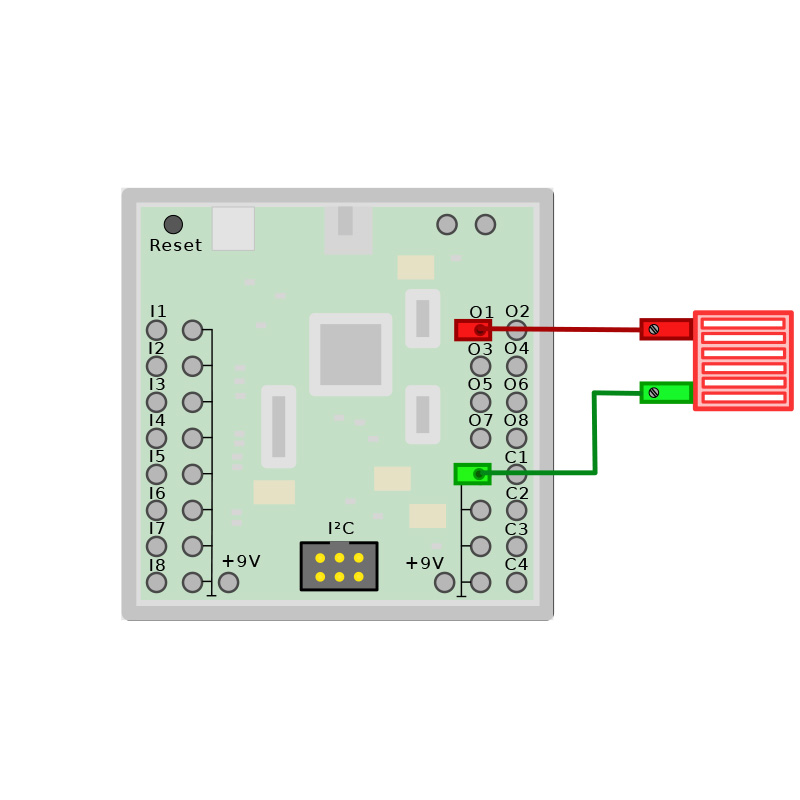
サンプルプログラム

ftDuino 2台通信

// ==  マスター側のプログラム ==
//  include  -- 必要ファイルの読み込み
#include <FtduinoSimple.h>
#include <Wire.h>

void setup() {
  Wire.begin();                       // マスターでI2Cを開始
}

 //  関数を作成
void set_output(int o, int v) { 
  Wire.beginTransmission(43);         // アドレスが 42 のI2Cデバイスにデータを送信
  Wire.write(0 + o - Ftduino::O1);    // O1 を指定
  Wire.write((v == Ftduino::HI) ? 1 : 0); // スイッチが押されて入れば 1 押されていないなら 0 を送信
  Wire.endTransmission();             //  転送終了
}

void loop() {
  //  I1 に接続されているスイッチの値を取得
  if (ftduino.input_get(Ftduino::I1))
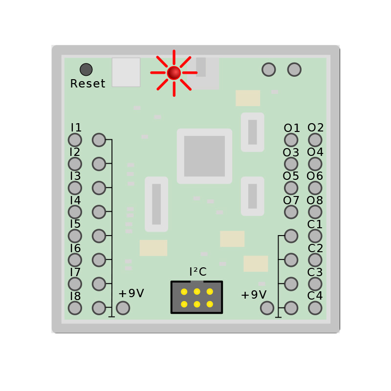
    set_output01(Ftduino::O1, Ftduino::HI); // 関数呼び出し
  else
    set_output01(Ftduino::O1, Ftduino::LO); // 関数呼び出し

  delay(10);
}

// ==============================================
// ==  スレーブ側のプログラム ==
//  include  -- 必要ファイルの読み込み
#include <FtduinoSimple.h>
#include <Wire.h>

void setup() {
  Wire.begin(43);     // アドレス 43 で スレーブ としてI2Cを開始
  // スレーブ側のデバイスが『マスター側のデバイスからの送信』を受信した際に呼び出される関数の登録
  Wire.onReceive(receiveEvent);
}
void loop() {
  delay(100);
}

void receiveEvent(int num) {
  // マスター側からいつでも呼び出される関数
  // データはI2C経由で送信 // setup() で登録されています

  if (Wire.available())//  最低1byte 必要 {
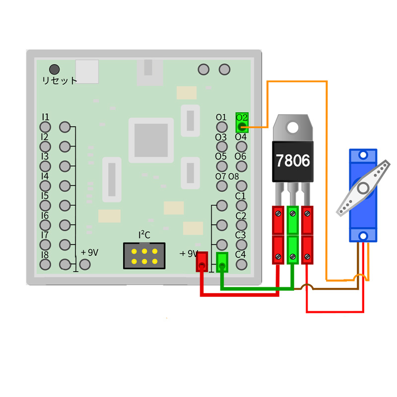
    // 最初の バイト はレジスタアドレス
    int addr = Wire.read();

  // アドレス0〜7のスイッチ   出力O1〜O8
  if ((addr >= 0) && (addr <= 7) && Wire.available()) {
    int value = Wire.read();  // 読み込み
    // 出力
    ftduino.output_set(Ftduino::O1 + addr, value ? Ftduino::HI : Ftduino::LO);
  }
}
}

サンプルプログラム

ftDuino 3台通信

// ==  マスター側のプログラム ==
//  include  -- 必要ファイルの読み込み
#include <FtduinoSimple.h>
#include <Wire.h>
void setup() {
  Wire.begin();    // マスターとして I2C開始
}
 //  関数を作成
void set_output(int o, int v) { 
  Wire.beginTransmission(43);         // アドレスが 42 のI2Cデバイスにデータを送信
  Wire.write(0 + o - Ftduino::O1);    // O1 を指定
  Wire.write((v == Ftduino::HI) ? 1 : 0); // スイッチが押されて入れば 1 押されていないなら 0 を送信
  Wire.endTransmission();             //  転送終了
}
//  関数を作成
void set_output02(int o, int v) {
  Wire.beginTransmission(44);        // アドレスが 44 のI2Cデバイスにデータを送信
  Wire.write(0 + o - Ftduino::O1);    // O1を指定
  Wire.write((v == Ftduino::HI) ? 1 : 0); // スイッチが押されているなら 1 押されていないなら 0
  Wire.endTransmission();             // 転送終了
}
void loop() {
  // スイッチの入力を取得
  if (ftduino.input_get(Ftduino::I1))
    set_output01(Ftduino::O1, Ftduino::HI);
  else
    set_output01(Ftduino::O1, Ftduino::LO);

  if (ftduino.input_get(Ftduino::I2))
    set_output02(Ftduino::O1, Ftduino::HI);
  else
    set_output02(Ftduino::O1, Ftduino::LO);
  delay(10);
}

// =================================
// ==  スレーブ1側のプログラム ==
//  include  -- 必要ファイルの読み込み
#include <FtduinoSimple.h>
#include <Wire.h>

void setup() {
  Wire.begin(43);      // アドレス 43 で スレーブ としてI2Cを開始
  // スレーブ側のデバイスが『マスター側のデバイスからの送信』を受信した際に呼び出される関数の登録
  Wire.onReceive(receiveEvent); 
}

void loop() {
  delay(100);
}
  // マスター側からいつでも呼び出される関数
  // データはI2C経由で送信 // setup() で登録されています
void receiveEvent(int num) {
    //  最低1byte 必要
  if(Wire.available()) {
    // 最初の バイト はレジスタアドレス
    int addr = Wire.read();

    // アドレス0〜7のスイッチ   出力O1〜O8
    if((addr >= 0) && (addr <= 7) && Wire.available()) {
      int value = Wire.read(); //  読み込み
      ftduino.output_set(Ftduino::O1+addr, value?Ftduino::HI:Ftduino::LO);
    }
  }
}

// ====================================
// ==  スレーブ2側のプログラム ==
//  include  -- 必要ファイルの読み込み
#include <FtduinoSimple.h>
#include <Wire.h>

void setup() {
  Wire.begin(44);      // アドレス 44 で スレーブ としてI2Cを開始
  // スレーブ側のデバイスが『マスター側のデバイスからの送信』を受信した際に呼び出される関数の登録
  Wire.onReceive(receiveEvent); 
}
void loop() {
  delay(100);
}

  // マスター側からいつでも呼び出される関数
  // データはI2C経由で送信 // setup() で登録されています
void receiveEvent(int num) {
  //  最低1byte 必要
  if(Wire.available()) {
    // 最初の バイト はレジスタアドレス
    int addr = Wire.read();

    // アドレス0〜7のスイッチ   出力O1〜O8
    if((addr >= 0) && (addr <= 7) && Wire.available()) {
      int value = Wire.read(); //  読み込み
      ftduino.output_set(Ftduino::O1+addr, value?Ftduino::HI:Ftduino::LO);
    }
  }
}

サンプルプログラム

Bluetooth

// CounterPorts/Bridge.ino
//
// Bridge between a bluetooth module connected to ftDuino counter ports C1
// (and optional C2)

void setup() 
{
    Serial.begin(9600);  // シリアルモニタへ
    Serial1.begin(9600); // Bluetoothから
};

void loop() 
{
    //  データがあれば  かつ シリアルモニタへ出力可能ならば
    while(Serial1.available() && Serial.availableForWrite())
    // 読み込み
      Serial.write(Serial1.read());
      
    if(Serial.available() && Serial1.availableForWrite())
      Serial1.write(Serial.read());
};

サンプルプログラム

Bluetooth コントロール

//  innclude ==  必要ファイルの読み込み  ==
#include <FtduinoSimple.h>

int data;  // 送られてくるデータの格納用変数

void setup()
{
  // シリアル通信
  Serial1.begin(9600);
};

void loop()
{
  while (Serial1.available()) {
    data = Serial1.read();
    
    if (data == '2') {
      Serial.println("");
      Serial.println("=============");
      ftduino.output_set(Ftduino::O1, Ftduino::HI); // O1が点灯
    }
    if (data == '1') {
      Serial.println("");
      Serial.println("=============");
      ftduino.output_set(Ftduino::O1, Ftduino::LO);//  O1が消灯
    }
    if (data == '8') {
      Serial.println("");
      Serial.println("=============");
      ftduino.output_set(Ftduino::O2, Ftduino::HI);//  O2が点灯
    }
    if (data == '4') {
      Serial.println("");
      Serial.println("=============");
      ftduino.output_set(Ftduino::O2, Ftduino::LO);//  O2が消灯
    }
  }
  delay(10);
};

サンプルプログラム

ラズパイと通信

//  include 必要ファイルのインクルード
#include <Wire.h>
#define addr 0x40

static int cmd = 0;
static byte buf[50];
static byte buf2[50];
static int num = 0;

void setup() {
  // i2c にスレーブとして接続
  Wire.begin(addr);
  Wire.onReceive(receive); // データがマスターから来た時
  Wire.onRequest(send); // マスターからリクエストが来た時
}

void loop() {
  // put your main code here, to run repeatedly:
  delay(100);
}

//  RaspberryPiへ送信
void send() {
  for (int i = 0; i < 10; i++) {
    Wire.write(i);
  }
}

//  RaspberryPiから受信
void receive(int n){
  num = n;
  // cmdを読み込み
  cmd = Wire.read();
  // cmdが0なら
  if(cmd == 0){
    // シリアルモニタへ出力
    for(int i = 0; i < n-1; i++){
      buf[i] = Wire.read();
      Serial.println(buf[i]);
    }
  }
}

// ====================== # Raspberrypi 側
import smbus   # i2c用のライブラリ
import time    # 時間関連のライブラリ
import RPi.GPIO as GPIO  # GPIOを使用するために使用
import random  # 数値のランダム生成に使用
import sys     # プログラムの終了・ファイルのアクセスなどに使用

GPIO.setwarnings(False) # 警告文が出ないようにする

i2c = smbus.SMBus(1)  # インスタンス化

# ftDuinoのアドレス
ft_addr = 0x40

while True:
    # ftDuinoへ送信
    send = []
    for i in range(10):
        send.append(random.randint(0,255))
    i2c.write_i2c_block_data(ft_addr, 0, send)
    #print(send)

    # ftDuinoから受信
    data = i2c.read_i2c_block_data(ft_addr,1,10)
    print(data)

    time.sleep(0.5)

    if KeyboardInterrupt:  # Ctrl + C が押されたとき
        GPIO.cleanup()  # GPIOピンを解放


sys.exit()  # プログラム終了
サンプルプログラム